Eureka AIR delivers breakthrough ideas for toughest innovation challenges, trusted by R&D personnel around the world.

A building roof siphon rainwater drainage system for energy recovery

A technology for energy recovery and drainage systems, applied in waterway systems, roof drainage, buildings, etc., can solve the problems that rainwater potential energy cannot be effectively converted and utilized, and increase the soil construction cost of drainage structures, so as to save soil construction costs, fast discharge, and high economy value effect

Active Publication Date: 2018-05-22
CHINA UNITED ENG
View PDF6 Cites 0 Cited by
  • Summary
  • Abstract
  • Description
  • Claims
  • Application Information

AI Technical Summary

Problems solved by technology

However, the siphon system has not yet been introduced into the roof rainwater power generation system
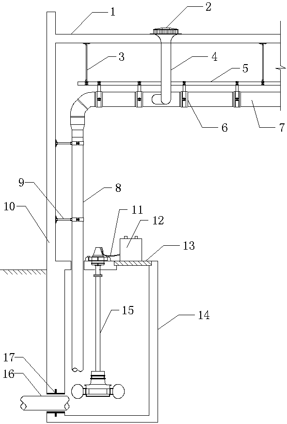
[0007] For the rainwater drainage system: the rainwater inspection well connected to the existing siphonic rainwater drainage system often needs to be equipped with special energy dissipation measures to offset the huge energy contained in the pressurized discharge pipe, which increases the civil construction cost of the drainage structure. Potential energy of rainwater cannot be effectively transformed and utilized

Method used


Image

  • A building roof siphon rainwater drainage system for energy recovery

Examples


Embodiment Construction

[0020] The present invention will be further described in detail below in conjunction with the accompanying drawings and examples. The following examples are explanations of the present invention and the present invention is not limited to the following examples.

[0021] Example.

[0022] see figure 1 In this embodiment, the building roof siphon rainwater drainage system that realizes energy recovery includes a siphon rainwater bucket 2 located in the roof gutter 1, a hanger 3 fixed on the floor below the roof gutter 1, a rainwater connecting pipe 4, and a suspension Beam 5, rainwater suspension pipe 7, suspension pipe clip 6 for fixing rainwater suspension pipe 7, rainwater standpipe 8, horizontal pipe clip 9 fixed on building wall 10, output wire 11, battery 12, setting There is the indoor rainwater inspection well 14 of movable manhole cover 13, the hydroelectric generator 15 that is installed in the indoor rainwater inspection well 14, the rainwater discharge pipe 16 tha...


PUM


Abstract

The invention relates to a building roof siphon type rainwater drainage system capable of achieving energy recovery. Currently, a building roof siphon type rainwater drainage system which is reasonable in structural design and capable of achieving energy recovery is not available. The building roof siphon type rainwater drainage system capable of achieving energy recovery is characterized by comprising a siphonic roof drain located in a center gutter, a hanging frame fixed to a floor slab below the center gutter, a rainwater connecting pipe, a hanger beam, a rainwater hanging pipe, hanging pipe clamps used for fixing the rainwater hanging pipe, a vertical rainwater pipe, horizontal pipe clamps, an output wire, a storage battery, an indoor rainwater inspection well and a hydro generator installed inside the indoor rainwater inspection well; the upper end of the rainwater connecting pipe is connected with the siphonic roof drain, and the lower end of the rainwater connecting pipe is connected with the hanging pipe clamps; the horizontal pipe clamps are fixed to the vertical rainwater pipe; the upper end of the vertical rainwater connecting pipe is connected with the rainwater hanging pipe; the lower end of the vertical rainwater pipe is located inside the indoor rainwater inspection well and matched with the hydro generator; the storage battery is connected with the hydro generator. According to the building roof siphon type rainwater drainage system capable of achieving energy recovery, the mechanical energy of rainwater is converted into electric energy, and the energy recovery efficiency is high.

Description

technical field [0001] The invention belongs to the field of rainwater resource regeneration and utilization, and relates to a rainwater drainage system for recovering rainwater energy, in particular to a building roof siphon rainwater drainage system for realizing energy recovery. Background technique [0002] In recent years, with the rapid development of the social economy, whether in the field of industrial production or in the civil field, large-scale public buildings such as multi-span factory buildings and complexes continue to emerge. In the above-mentioned architectural design process, the rainwater discharge of long-span roofs has increasingly become a hot spot of attention, mainly focusing on the rapid discharge of rainwater and the utilization of water resources. [0003] For the rapid discharge of rainwater, at present, the siphon rainwater drainage system can better solve the rainwater discharge on the roof under the condition of large catchment area. It is a p...

Claims


Application Information

Patent Timeline
Patent Type & Authority Patents(China)
IPC IPC(8): F03B13/00E04D13/04E04D13/08E03F1/00
Inventor 龚灵潇刘志娟肖大伟
Owner CHINA UNITED ENG
Why Eureka
Eureka Blog
Learn More