Reconstruction method and structure for reconstructing wet-type cooling tower into dry-type cooling tower in power plant

A dry cooling tower, wet cooling technology, applied in water shower coolers, direct contact heat exchangers, heat exchanger types, etc., can solve problems such as large air resistance, poor economy, and inconsistent service life of unit equipment , to achieve the effect of reducing air resistance, low cost of civil construction, and increasing effective height

Pending Publication Date: 2019-01-18
NORTHWEST ELECTRIC POWER DESIGN INST OF CHINA POWER ENG CONSULTING GROUP
View PDF0 Cites 0 Cited by
  • Summary
  • Abstract
  • Description
  • Claims
  • Application Information

AI Technical Summary

Problems solved by technology

In these power plants, the unit has often been in operation for many years. If the existing natural ventilation wet cooling tower is removed and a dry cooling tower is newly built, there will be problems such as inconsistency between the service life of the new cooling tower and the existing unit equipment, and poor economic efficiency. It is often desirable to continue utilizing existing natural draft wet cooling towers
[0003] Compared with the specially designed air cooling tower, the vertical height of the air inlet of the traditional natural ventilation wet cooling tower is obviously much smaller. If it is directly used as an air cooling tower, the air resistance is relatively large due to the limitation of the total area of ​​the air inlet

Method used


Image

  • Reconstruction method and structure for reconstructing wet-type cooling tower into dry-type cooling tower in power plant
  • Reconstruction method and structure for reconstructing wet-type cooling tower into dry-type cooling tower in power plant
  • Reconstruction method and structure for reconstructing wet-type cooling tower into dry-type cooling tower in power plant

Examples


Embodiment Construction

[0029] The present invention will be described in further detail below in conjunction with the accompanying drawings.

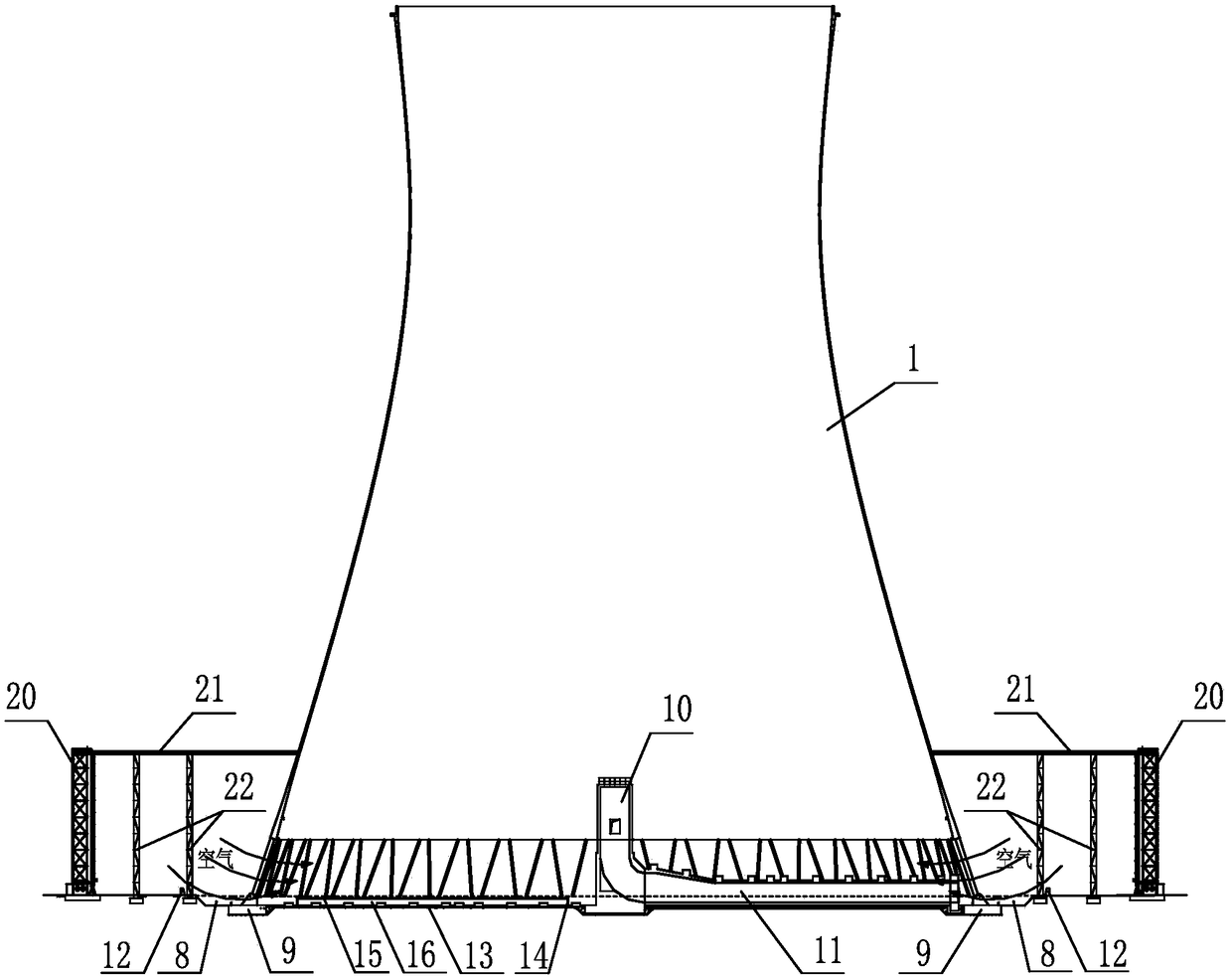
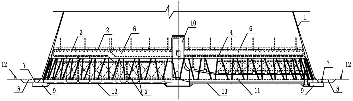
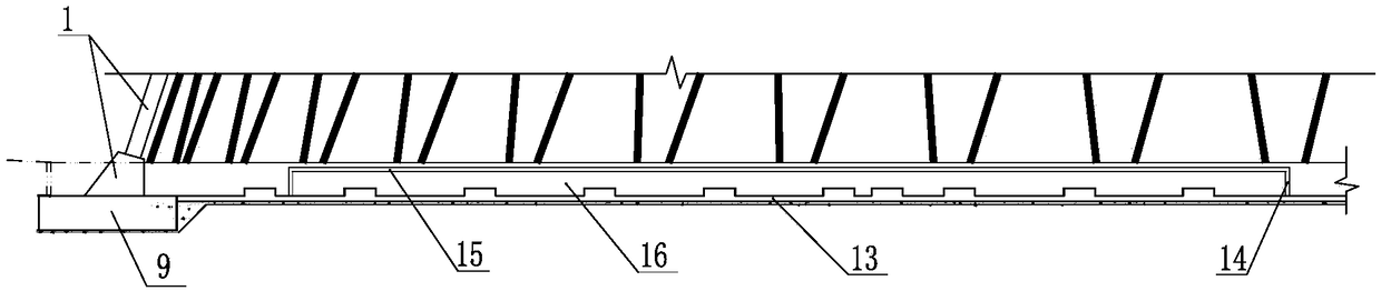
[0030] see Figure 1-4 , the invention provides a method for transforming a wet cooling tower into a dry cooling tower in a power plant, comprising the following steps:

[0031] Keep the cooling tower body 1 of the existing natural ventilation wet cooling tower; remove the water eliminator 2, water distribution piping system and nozzle 3, water spray filler and bracket 4, and frame beams and columns of the existing natural ventilation wet cooling tower etc.; remove the pool wall 7 of the sump pool at the bottom of the existing naturally ventilated wet cooling tower; excavate the surrounding soil 8 to the top surface elevation of the ring base 9 outside the pool wall of the existing naturally ventilated wet cooling tower sump; The heat exchanger 20 is arranged in a circular or non-circular plane, and is vertically arranged on the outer circumference of the co...


PUM


Abstract

The invention discloses a reconstruction method and structure for reconstructing a wet-type cooling tower into a dry-type cooling tower in a power plant. The reconstruction method comprises the following steps: (1) reserving a cooling tower body of an existing natural ventilation wet-type cooling tower; (2) building a side wall and a top plate on a bottom plate of a bottom water collection tank ofthe natural ventilation wet-type cooling tower to form a closed water storage tank; integrally laying a waterproof layer on the inner surface of the water storage tank to form a closed underground water tank; (3) distributing an air cooling system underground pipe network inside or outside the natural ventilation cooling tower; (4) vertically distributing newly added air cooling heat exchangers on an outer periphery of the cooling tower body; and (5) establishing an extension platform between the top of the air cooling heat exchangers and the cooling tower body, and supporting the extension platform on vertical supporting columns outside the cooling tower body. According to the reconstruction method of the invention, an existing civil construction facility of an old tower is sufficientlyutilized, no new air cooling tower is built, and the civil construction cost is low; and the effective height of an air inlet of the cooling tower can be maximally increased, and the air resistance can be reduced.

Description

technical field [0001] The invention belongs to the field of industrial cooling design, and relates to a transformation method and structure for changing a wet cooling tower into a dry cooling tower in a power plant. Background technique [0002] For the purpose of saving water or limited by water policy, some power plants using wet secondary circulation cooling system put forward the transformation requirement of wet cooling system to air cooling system. In these power plants, the unit has often been in operation for many years. If the existing natural ventilation wet cooling tower is removed and a dry cooling tower is newly built, there will be problems such as inconsistency between the service life of the new cooling tower and the existing unit equipment, and poor economic efficiency. It is often desirable to continue utilizing existing natural draft wet cooling towers. [0003] Compared with the specially designed air cooling tower, the vertical height of the air inlet ...

Claims


Application Information

Patent Timeline
IPC IPC(8): F28C1/00F28F25/00F28F25/02
CPCF28C1/00F28F25/00F28F25/02
Inventor 侯宪安姚友成李江斌赵拴荣李诚郑经纬张海刘振盛杨迎哲彭兢
Owner NORTHWEST ELECTRIC POWER DESIGN INST OF CHINA POWER ENG CONSULTING GROUP
Why Eureka
Try Eureka