Semi-active electromagnetic particle damping shock absorber for railway vehicle

A semi-active, rail vehicle technology, applied in the field of rail vehicles, can solve the problems of high manufacturing precision, inability to adjust, and high cost, and achieve the effects of reducing stiffness, increasing stability, and improving adaptability to harsh environments

Inactive Publication Date: 2016-01-06
TONGJI UNIV
View PDF7 Cites 15 Cited by
  • Summary
  • Abstract
  • Description
  • Claims
  • Application Information

AI Technical Summary

Problems solved by technology

[0003] At present, the first series of damping shock absorbers of bullet trains use oil pressure shock absorbers, which have some disadvantages: 1. High manufacturing precision and high cost; 2. The damping value is fixed and cannot be adjusted according to actual road conditions; 3. For low-amplitude High-frequency or high-amplitude and low-frequency vibrations cannot be effectively controlled; some shock absorbers are mainly imported, costly, and cannot respond to market demand in a timely manner

Method used


Image

  • Semi-active electromagnetic particle damping shock absorber for railway vehicle
  • Semi-active electromagnetic particle damping shock absorber for railway vehicle
  • Semi-active electromagnetic particle damping shock absorber for railway vehicle

Examples


Embodiment 1

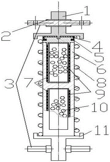
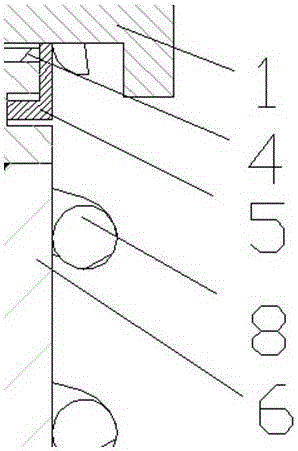
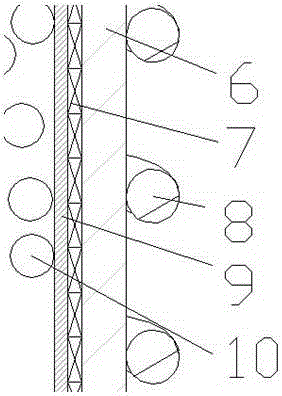
[0026] Embodiment 1: A semi-active particle damping shock absorber for a rail vehicle, such as figure 1 , figure 2 with image 3 As shown, it includes a shell 6, the shell 6 is made of a cylindrical composite damping steel plate, and the shell 6 is divided into upper and lower cavities; the cavity is separated by a wear-resistant metal interlayer 9, and the wear-resistant metal interlayer 9 is installed In the cavity of the shell 6, there is an interference fit between the two; the electromagnetic coil 7 is embedded in the groove on the wear-resistant metal interlayer 9 and the inner wall of the shell 6; the volume ratio of the wear-resistant metal interlayer 9 is 50-70 % of vibration damping particles 10, the selection of its parameters should be determined according to the actual vehicle conditions, and the vehicle vibration environment is relatively severe and complex, and at the same time, viscoelastic material particles or non-metallic particles can be added to adopt it...


PUM


Abstract

The invention discloses a semi-active electromagnetic particle damping shock absorber for a railway vehicle, and belongs to the technical field of vehicle shock absorption. A certain shock absorption effect is achieved on transverse vibration and longitudinal vibration while vertical shock absorption is provided. The semi-active electromagnetic particle damping shock absorber comprises an upper cover plate type connector, a lower cover plate type connector, a rubber spherical hinge, pin shafts, an external round spring, a shell, shock absorption particles, wear-proof metal separation layers and inductance coils. The shell is divided into an upper groove and a lower groove, the wear-proof metal separation layers are arranged in the upper groove and the lower groove, the shock absorption particles of a certain volume and lubrication oil of a certain amount are arranged in the separation layers, and the inductance coils are arranged in the wear-proof metal separation layers and the grooves. The upper connector is fixedly connected with one end of the shell. The lower connector and the other end of the shell are welded. The rubber spherical hinge and the pin shafts are assembled, and the shock absorber and a bogie are connected together according to standards. Through the damping effect generated by collisions between the particles and collisions between the particles and the wall of the shell, vibration transmission from wheels to a framework is rapidly attenuated, and the good shock absorption effect in different directions is achieved. Meanwhile, the size of an electrification magnetic field can be changed according to changes of a running line, then the damping value of the shock absorber is changed, semiautomatic control over the damping effect is achieved, high reliability and large safety redundancy are achieved, and the semi-active electromagnetic particle damping shock absorber adapts to various severe environments.

Description

technical field [0001] The invention relates to the field of rail vehicles, and relates to a semi-active electromagnetic particle damping shock absorber for rail vehicles. Background technique [0002] Although the existing particle damping shock absorber has the characteristics of simple structure and obvious damping effect, metal particles collide with each other during its working process, which easily causes wear of the structure and particles, which reduces its life. By applying a DC electromagnetic field, the momentum exchange between the particle body and the shell is increased, the suppression of structural vibration is improved, and the contact pressure between the ferromagnetic particles is increased, the friction force is increased, and the friction loss of the damper is increased. can. By changing the magnitude of the current in the electromagnetic field, the damping force can be adjusted in a wide range. And it has strong adaptability to harsh environments, an...

Claims


Application Information

Patent Timeline
Patent Type & Authority Applications(China)
IPC IPC(8): F16F13/00F16F13/26F16F7/01F16F6/00
Inventor 郑钰馨华滨滨李梦如卜王辉朱文翔奚鹰
Owner TONGJI UNIV
Why Eureka
Try Eureka