
Thermal type gas mass flow-meter based on adjustable constant current source

A gas mass flow, constant current source technology, applied in indirect mass flow meters, mass flow measurement devices, etc., can solve problems affecting bridge balance, heating power increase circuit, and insensitivity to flow changes, etc.

Inactive Publication Date: 2016-01-06
TIANJIN UNIV
View PDF3 Cites 6 Cited by
  • Summary
  • Abstract
  • Description
  • Claims
  • Application Information

AI Technical Summary

Problems solved by technology

The constant temperature difference type has two main disadvantages: first, it adopts the Wheatstone bridge structure, and when the ambient temperature changes, it will affect the balance of the bridge, which is manifested as zero instability and small flow accuracy cannot be guaranteed, and a corresponding temperature compensation circuit must be added; The second is that the upper limit of the flow rate is limited. As the flow rate continues to increase, the heating power also increases accordingly. When the heating power is too large, it will increase the difficulty of circuit design and affect the stability of the circuit.
When the fluid flow rate is small or zero, if the heating current is too large, the speed measuring probe will be overheated, and the ambient temperature will rise significantly, so the natural convection heat transfer between the speed measuring probe and the temperature measuring probe cannot be ignored; when the fluid When the flow rate is large, if the heating current is too small, the fluid will take away too much heat, so that the temperature difference between the temperature measuring probe and the speed measuring probe is very small, making the probe insensitive to the change of flow rate

Method used


Image

  • Thermal type gas mass flow-meter based on adjustable constant current source
  • Thermal type gas mass flow-meter based on adjustable constant current source
  • Thermal type gas mass flow-meter based on adjustable constant current source

Examples


Embodiment Construction

[0026] The present invention will be described below in conjunction with the accompanying drawings and embodiments.

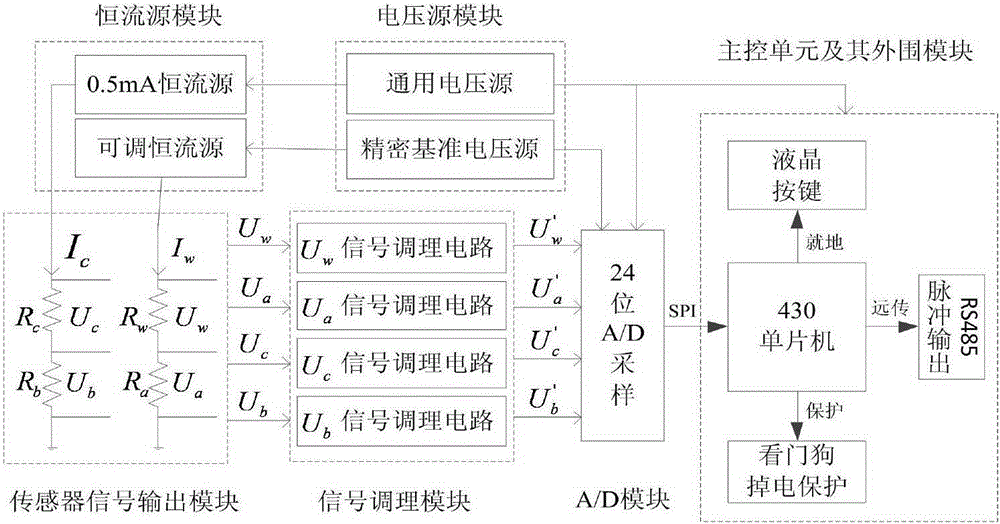
[0027] The mass flowmeter of the present invention, its complete machine circuit principle is as follows figure 1 shown.

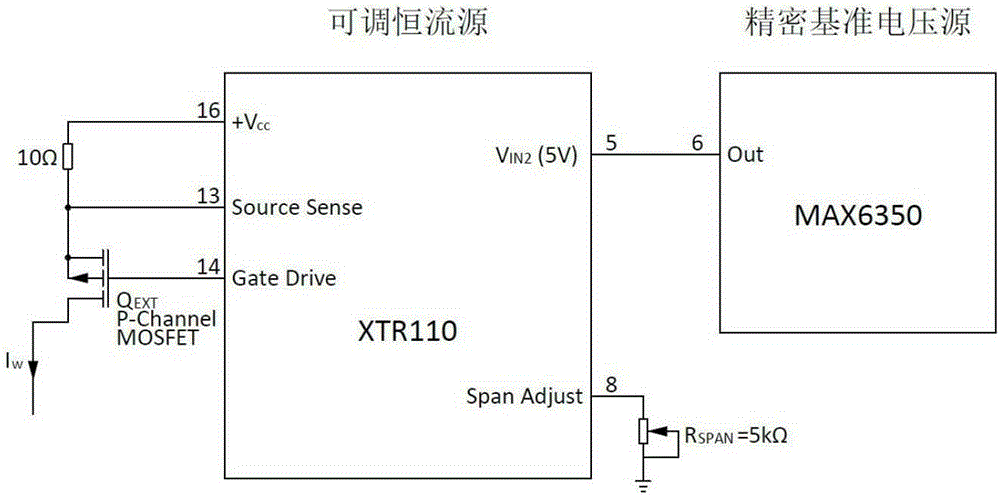
[0028] The whole machine is divided into sensor signal output module, constant current source module, voltage source module, main control unit and its peripheral modules, A / D module, and signal conditioning module. R C is the resistance value of the temperature measuring probe, from which we can know the temperature of the gas medium Tc; R W is the resistance value of the speed measuring probe, from which we can know the temperature Tw of the speed measuring probe; R a , R b It is the reference resistor, the resistance value is 100Ω, the accuracy is 0.01%, and the temperature drift is 5ppm.

[0029] R c = U c * ...


PUM


Abstract

The invention relates to a thermal type gas mass flow-meter based on an adjustable constant current source, which comprises a constant current source module, a sensor signal output module, a signal regulating module, an A / D sampling module and a main control unit, wherein a sensor module is constituted of a speed measuring probe platinum thermal resistor, a temperature measuring probe platinum thermal resistor, a reference resistor in serials connection with the speed measuring probe platinum thermal resistor and a reference resistor in serials connection with the speed measuring probe thermal resistor; based on voltage values loaded on the four resistors, four ways of voltage signals are correspondingly outputted; the signal regulating module comprises a four-way regulating circuit; the four ways of regulated voltage signals that meet the sampling requirements are sent into the A / D sampling module for analog-digital transformation; the voltage signals are sent to the main control unit after analog-digital transformation; the flow value is calculated by the main control unit; and the constant current source module comprises a constant current source for providing constant driving electric current for a temperature measuring probe branch and an adjustable constant current source for providing adjustable driving electric current for a speed measuring probe. According to the invention, the thermal type gas mass flow-meter provided herein has the characteristics of accurate measurement and wide measuring range.

Description

technical field [0001] The invention belongs to the technical field of flow measurement and relates to a gas mass flow meter. Background technique [0002] The thermal gas mass flowmeter is a direct mass flowmeter, which has many advantages such as wide measurement range, small pressure loss, high reliability, can measure mixed gas, suitable for various pipelines and overload without damage, etc., and has been widely used [1] . At present, the research of thermal gas mass flowmeter mainly focuses on four aspects: one is the temperature technology compensation research; the second is the sensor design research, using different materials and processing techniques to ensure the accuracy and reliability of the measurement; the third is the measurement Methods and Data Processing Research [2] , under the premise of ensuring the measurement resolution and accuracy, process the collected data; the fourth is the sensor modeling research, if the corresponding model of the sensor ca...

Claims


Application Information

Patent Timeline
IPC IPC(8): G01F1/86
Inventor 张涛徐英吴海涛
Owner TIANJIN UNIV
Learn More