A drip irrigation belt retracting device

The technology of drip irrigation belt and pole is applied in the field of drip irrigation belt retracting device, which can solve the problems of high cost, time-consuming, laborious, and easy scaling of the dripper, and achieve the effects of low cost, avoidance of clutter, and easy disassembly.

Active Publication Date: 2020-02-04
付峻岭
View PDF14 Cites 1 Cited by
  • Summary
  • Abstract
  • Description
  • Claims
  • Application Information

AI Technical Summary

Problems solved by technology

Its disadvantage is that the dripper is easy to scale and block, so the water source should be strictly filtered
[0003] my country is a large agricultural country, and it is also a country with serious water shortage. Therefore, water-saving drip irrigation technology is being used more and more widely. Every year, a large number of drip irrigation belts are left in the farmland, which need to be recycled and reused. It is all done manually, which is time-consuming and laborious. National patents CN201309780Y, CN102633165B and CN102935967B are all about mechanical devices for recycling drip irrigation belts. The biggest difference from this case is that the recycling mechanism is driven by the gearbox and drive shaft to complete the work. Price The cost is high, and the later maintenance cost is high. In this case, the walking wheel is directly driven by the chain to drive the rotating screw to complete the belt winding work, instead of manual work to realize the mechanized rolling of the drip irrigation belt. There are many strips, and each longitudinal furrow is also very long. During the rolling process, a new type of rolling device with simple structure, low cost, neat rolling, high efficiency, good safety performance, and avoiding messy phenomena in the rolling process is required.

Method used


Image

  • A drip irrigation belt retracting device
  • A drip irrigation belt retracting device
  • A drip irrigation belt retracting device

Examples


Embodiment Construction

[0023] Below by non-limiting embodiment and in conjunction with accompanying drawing, invention is further described:

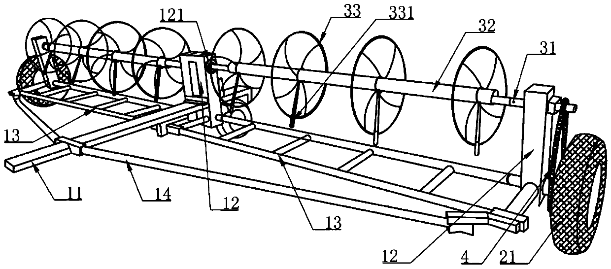
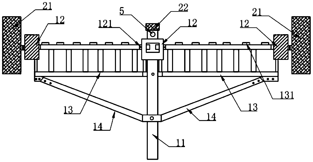
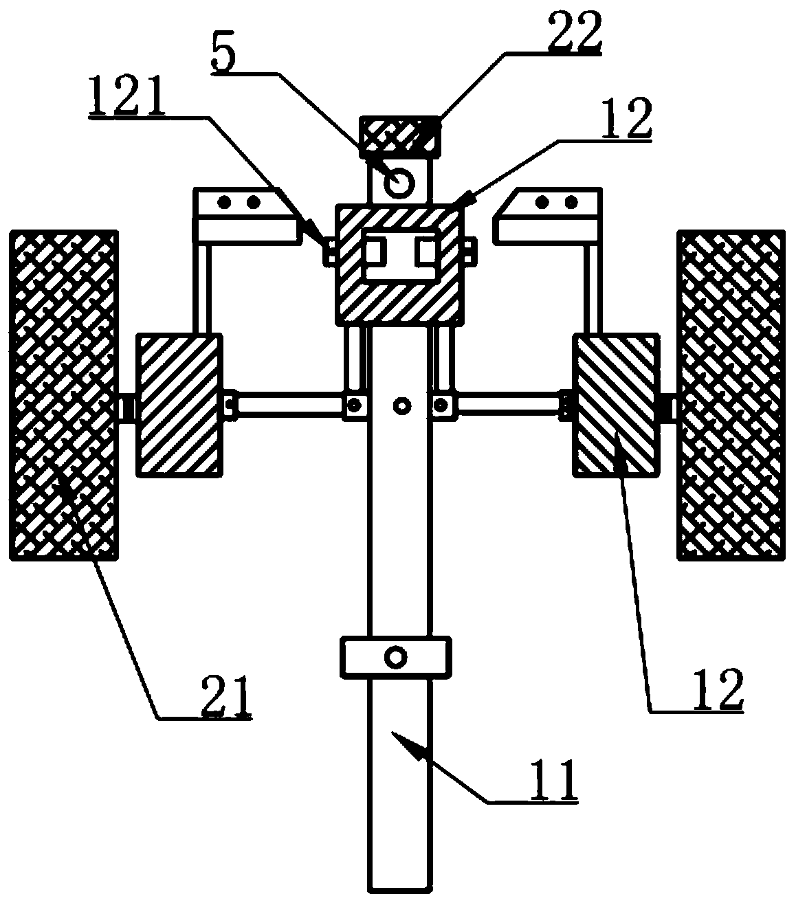
[0024] Such as Figure 1-4 As shown, a drip irrigation belt retracting device is driven by a tractor output power and the structure is composed of a support mechanism, a retracting mechanism and a walking mechanism, the retracting mechanism and the traveling mechanism are arranged horizontally, and the total width is 6.5- 7.5 meters; the supporting mechanism is to be used to connect the main rod 11 of the traction mechanism tractor, three vertical rods 12, two secondary rods 13 connected and fixed with the bottom ends of the three vertical rods 12 and for the main rod 11, the left and right two The connecting rod 14 that side vertical rod 12 is connected is made of; The retracting mechanism is to be made of rotating screw rod 31, retracting rod 32 and several circular fixed catches 33 that are arranged horizontally on the supporting mechanism vertical rod 12;...


PUM


Abstract

The invention discloses a drip irrigation belt winding device. The drip irrigation belt winding device is structurally composed of a supporting mechanism, a winding mechanism and a walking mechanism,wherein the winding mechanism and the walking mechanism are transversely arranged and the total width is 6.5 to 7.5m; the supporting mechanism is composed of a main rod (11), three vertical rods (12),two secondary rods (13) which are fixedly connected with the bottom end parts of the three vertical rods (12) and a connecting rod (14) for connecting the main rod (11) and the vertical rods (12) atthe left and right sides; the winding mechanism is composed of a rotary screw rod (31) which is transversely arranged on the vertical rods (12) of the supporting mechanism, a winding rod (32) and a plurality of round fixed blocking pieces (33); the walking mechanism is composed of walking wheels (21) which are connected with the vertical rods (12) at the left and right sides of the supporting mechanism and a walking wheel (22) at one end of the main rod (11). According to the winding device disclosed by the invention, power is output through a tractor to drag, the recycling speed and recyclingquality of a drip irrigation belt are improved and impurities are reduced.

Description

technical field [0001] The invention relates to the technical field of agricultural machinery, in particular to a retracting device for a drip irrigation belt. Background technique [0002] Drip irrigation is a precision irrigation method that uses a low-pressure pipeline system to transport water directly to the field, and then through the dripper, orifice or drip irrigation belt installed on the capillary, the water is evenly and slowly distributed drop by drop. Drop into the soil near the root zone of the crops, so that the soil in the most developed root system of the crops often maintains a suitable humidity, so that the water, fertilizer, gas, heat, and microbial activities of the soil are always in good condition, creating favorable conditions for high and stable crop yields. It is currently the most effective water-saving irrigation method in arid and water-scarce areas, and its water utilization rate can reach 95%. Compared with sprinkler irrigation, drip irrigatio...

Claims


Application Information

Patent Timeline
Patent Type & Authority Patents(China)
IPC IPC(8): B65H75/42B65H75/44
CPCB65H75/425B65H75/4481B65H2701/333
Inventor 付峻岭
Owner 付峻岭
Why Eureka
Try Eureka