Robust broadband self-adaptive beamforming method used for ultrasound imaging

An adaptive beam and ultrasonic imaging technology, applied in radio wave measurement systems, instruments, etc., can solve problems affecting the robustness of the method, phase distortion, and limited performance improvement

Inactive Publication Date: 2016-01-06
INST OF ACOUSTICS CHINESE ACAD OF SCI
View PDF2 Cites 13 Cited by
  • Summary
  • Abstract
  • Description
  • Claims
  • Application Information

AI Technical Summary

Problems solved by technology

In order to improve the quality of ultrasound imaging, the minimum variance adaptive beamforming method has received extensive attention, but this method faces the following two main problems: (1) The classic minimum variance beamforming method is proposed based on the narrowband signal model However, echo signals in the field of ultrasonic imaging generally belong to the category of broadband signals, so directly applying the minimum variance beamforming method to ultrasonic imaging does not fully demonstrate the advantages of the original method; (2) For imaging of inhomogeneous media There are often phase distortions in the process, which leads to certain errors in the estimation of the covariance matrix and steering vector in the minimum variance beamforming method, which in turn affects the robustness of the method, making it difficult to achieve ideal performance in more complex application environments
However, the above methods are all focused on processing in the time domain, and have not fully considered the broadband characteristics of ultrasonic echo signals, nor have they been able to effectively estimate the mismatched steering vector under the condition of phase distortion, resulting in limited performance improvement.

Method used


Image

  • Robust broadband self-adaptive beamforming method used for ultrasound imaging
  • Robust broadband self-adaptive beamforming method used for ultrasound imaging
  • Robust broadband self-adaptive beamforming method used for ultrasound imaging

Examples


Embodiment Construction

[0053] The technical solutions of the present invention will be described in further detail below in conjunction with the accompanying drawings and embodiments.

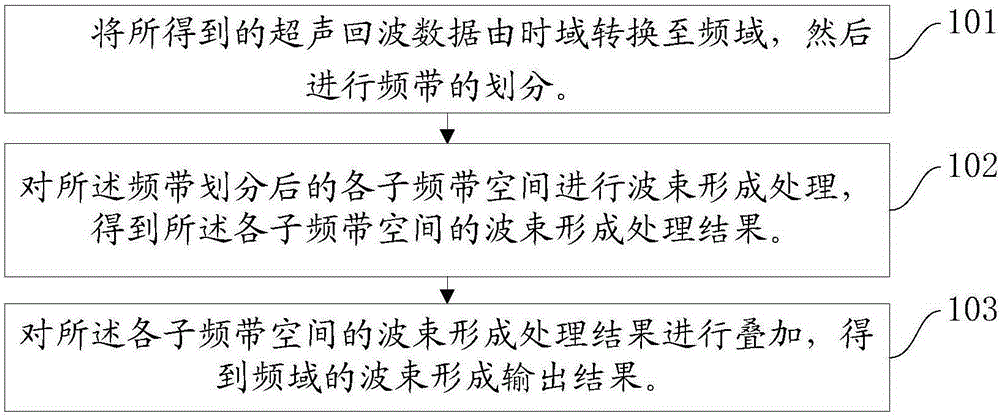
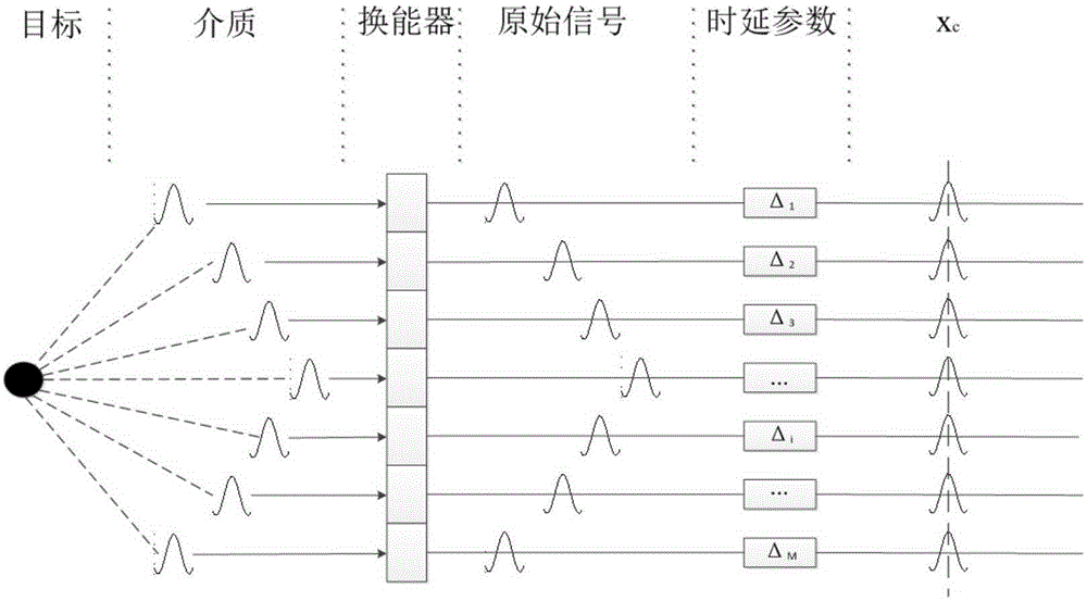
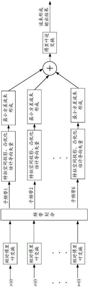
[0054] figure 1It is a schematic flowchart of an adaptive beamforming method provided by an embodiment of the present invention, and the embodiment of the present invention is applied to ultrasound imaging in B mode. The ultrasonic transducer array with M array elements at equal intervals works in the B-mode imaging linear scanning mode, and performs beamforming processing on the received echo data, and each scan line corresponds to the received signal of M array elements (that is, M is the number of array elements), and the number of samples of each array element is N, and the echo data received by all array elements corresponding to each scan line under B-mode ultrasonic imaging can be described by an M*N matrix . It should be noted that these echo data in the time domain have been preprocessed with time delay, ...


PUM


Abstract

The invention relates to a robust broadband self-adaptive beamforming method used for ultrasound imaging. The method comprises the steps that acquired ultrasonic echo data are converted from time domain to frequency domain, and band dividing is carried out; the covariance matrix of each subband divided from the band is calculated; according to the acquired covariance matrix, a feature space decomposition method is used to project an assumed steering vector into a signal subspace; a convex optimization method is used to estimate a true steering vector; the basic principle of a minimum variance method is used to acquire the beamforming processing result of each subband space; and the beamforming processing results of subband spaces are superimposed and are converted to time domain to acquire a final imaging output result. According to the invention, the broadband characteristic of an ultrasonic echo signal is fully used; the steering vector in real environment is reconstructed in frequency domain, so that the steering vector can have a robust performance in the case of phase distortion; and the ultrasound imaging quality can be improved under a non-homogeneous media.

Description

technical field [0001] The invention relates to the fields of medical ultrasonic diagnosis, ultrasonic non-destructive testing and the like, and in particular to a robust broadband adaptive beamforming method applied to ultrasonic imaging. Background technique [0002] The traditional medical ultrasonic diagnosis and ultrasonic non-destructive testing systems generally use the beamforming method of delay and superposition. This method is simple, reliable and easy to implement, but its performance is relatively general. In order to improve the quality of ultrasound imaging, the minimum variance adaptive beamforming method has received extensive attention, but this method faces the following two main problems: (1) The classic minimum variance beamforming method is proposed based on the narrowband signal model However, echo signals in the field of ultrasonic imaging generally belong to the category of broadband signals, so directly applying the minimum variance beamforming meth...

Claims


Application Information

Patent Timeline
Patent Type & Authority Applications(China)
IPC IPC(8): G01S7/526G01S7/52
CPCG01S7/52025G01S7/526
Inventor 夏新源李平孟晓辉理华
Owner INST OF ACOUSTICS CHINESE ACAD OF SCI
Why Eureka
Try Eureka