Method for reducing heating of electric joint and copper bars adopting method

A technology for electrical connectors and heating devices, applied in electrical components, circuits, connections, etc., can solve problems such as difficult realization, limited effect, and reduction of heat generation.

Active Publication Date: 2016-01-06
CHENGDU SHENLAN HIGH TECH DEV
View PDF8 Cites 5 Cited by
  • Summary
  • Abstract
  • Description
  • Claims
  • Application Information

AI Technical Summary

Problems solved by technology

This structural form cannot reduce heat generation before the busbar enters the connection, and it is not easy to reali

Method used


Image

  • Method for reducing heating of electric joint and copper bars adopting method
  • Method for reducing heating of electric joint and copper bars adopting method
  • Method for reducing heating of electric joint and copper bars adopting method

Examples


Embodiment Construction

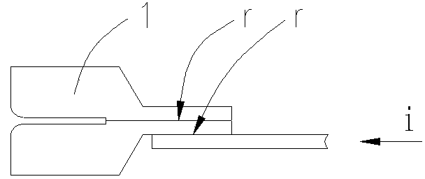
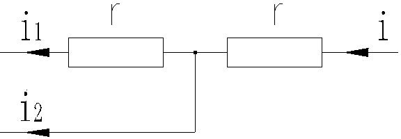
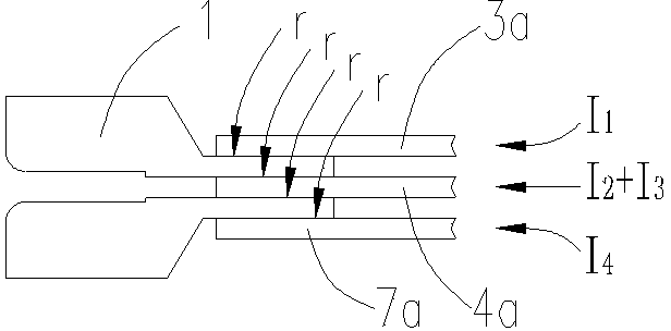
[0031] In a pure resistance circuit, it is assumed that the contact surface resistance and contact pressure between conductors are constant, ignoring the DC resistance of the conductors, according to the electrical power formula P=I 2 r, the heating power P of the electrical joint contact resistance r is proportional to the square of the current I(i), and is proportional to the contact resistance r. figure 1 It is a schematic diagram of the connection between the two wire lugs 1 and the copper bar of the existing circuit, from figure 2 The equivalent circuit diagram of resistors in series shows that: i=i 1 + i 2 ,i 1 = i, so, ∑P 1~2 = i 2 r+( i) 2 r= i 2 r; image 3 It is a schematic diagram of the connection between two wire lugs 1 and three copper bars, from Figure 4 The parallel equivalent circuit diagram of resistors shows that: I 1 =I 2 =I 3 =I 4 = I, so, ΣP 1~4 =4x(1 / 4I) 2 r= I 2 r; ΣP 1~2 / ∑P 1~4 =5, the contact heating power is the existing...


PUM


Abstract

The invention relates to a method for reducing heating of an electric joint, and copper bars adopting the method for reducing the heating of the electric joint. Serial connection of contact resistors of conductors of the electric joint is changed into parallel connection, and a single-face feed connection mode is changed into a double-face or multi-face feed connection mode, so a current density of each contact face is reduced, and the object of heating reduction is achieved. On the basis that the current-carrying capacity of the cross section of each conductor is guaranteed, a busbar connection piece adopts a thin copper plate folded, bent and flattened structural piece, a change for adaption of the fact that an electric element is connected to a copper bars structural piece is comprised, transition plates and backing plates are increased, copper materials are saved, good heat radiation performance is also possessed, and certain practical value especially in frequency converter structure thermal design is possessed.

Description

technical field [0001] The invention relates to a method for reducing heat generation of an electrical joint. The copper bar of the electrical joint is changed from single-side feeding to double-side or multi-side feeding, so as to reduce the current flowing through the unit contact surface. [0002] The invention also relates to a copper bar for reducing heat generation of electrical joints. The bus bar connector is folded and flattened by copper plates, which includes the change of the structural parts of the copper bar connecting electrical components, and the addition of a transition plate and a backing plate. Background technique [0003] At present, the power electronics industry is developing rapidly. Taking high-voltage and low-voltage inverters as an example, the use of high-power modules requires more compact and miniaturized chassis and cabinets. The first thing to bear the brunt of the heat dissipation problem is to reduce the heat generated by electrical connecto...

Claims


Application Information

Patent Timeline
IPC IPC(8): H01R43/00H01R25/16
Inventor 刘永言张倩谭蕴阳
Owner CHENGDU SHENLAN HIGH TECH DEV
Why Eureka
Try Eureka