Housing for an electrical machine

A shell and shell wall technology, applied in the direction of casing/housing/support, electrical components, electromechanical devices, etc.

Active Publication Date: 2016-01-06
SIEMENS AG
View PDF9 Cites 2 Cited by
  • Summary
  • Abstract
  • Description
  • Claims
  • Application Information

AI Technical Summary

Problems solved by technology

Furthermore, the arrangement of the terminal box is restricted, and the terminal bo

Method used


Image

  • Housing for an electrical machine
  • Housing for an electrical machine
  • Housing for an electrical machine

Examples


Embodiment Construction

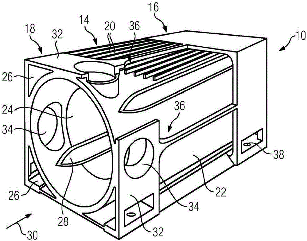
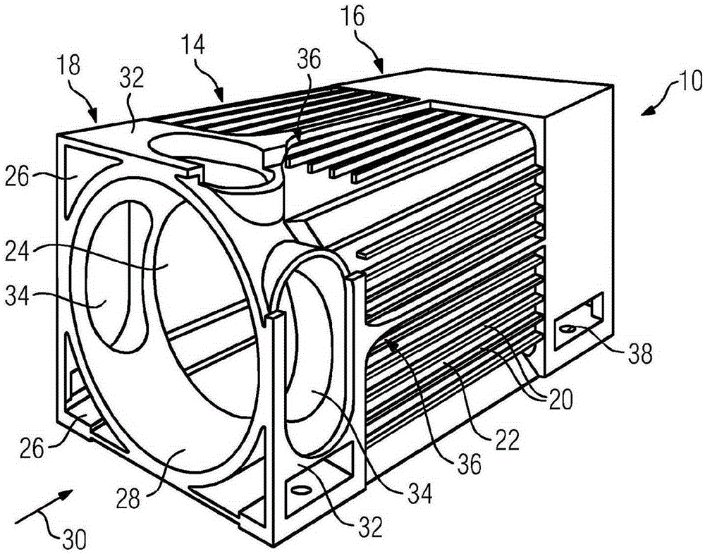
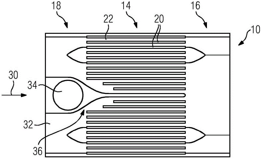
[0042] figure 1 The housing 10 for the electric motor 12 is shown in perspective. Housing 10 of electric machine 12 is divided into three regions 14 , 16 and 18 . In a cooling region 14 , which corresponds to a central region of the housing 10 , the housing comprises a plurality of cooling fins 20 , which are presently shown only in the upper region of the housing 10 . The cooling fins 20 are arranged on the outer surface of the housing wall 22 . The housing wall 22 essentially has a hollow cylindrical shape. The housing 10 can be made of gray cast iron or steel, for example. Because the housing 10 in the interior 24 has a substantially circular cross section, the housing 10 can be produced by means of turning.

[0043] Furthermore, the housing 10 has a coolant supply region 16 , which leads to the cooling region 14 . The coolant supply area 16 has a rectangular or square cross section. In the coolant supply region 16 there is at least one channel which serves to supply ...


PUM


Abstract

The invention relates to a housing (10) for an electrical machine (12) having a cooling region (14), in which a plurality of cooling fins (20) for guiding a coolant flow are arranged on an outer face of a housing wall (22), the housing comprising a coolant supply region (16), which adjoins the cooling region (14) on a first side of the cooling region (14) and which has at least one duct (48) for supplying the coolant flow to the cooling fins (20) of the cooling region (14), and a coolant discharge region (18), which adjoins the cooling region (14) on a second side of the cooling region (14) opposite the first side and which has at least one duct (26) for discharging the coolant flow from the cooling fins (20) of the cooling region.

Description

technical field [0001] The invention relates to a housing for an electric motor. Furthermore, the invention relates to an electric machine. Background technique [0002] To date, motors in various embodiments are available on the market. In this case, however, self-ventilated or externally ventilated electric motors, which are usually designed with classic ribbed housings, form the largest share. This housing shape has proven to be extremely good in the past, but accordingly no longer meets current requirements today, since many problems can no longer be solved so easily or simply cannot be transferred to new requirements. [0003] For example, electric machines are known which have rib housings made of gray cast iron and which can be cooled by means of external fan packs. Here, the return channel is integrated in the housing. In addition, the housing provides a mounting surface for the terminal box or an auxiliary terminal box. In this case, the outer fan group can gen...

Claims


Application Information

Patent Timeline
IPC IPC(8): H02K5/18H02K5/22H02K9/14
CPCH02K5/18H02K5/22H02K9/14H02K5/20
Inventor 托马斯·科克赖纳·格里勒恩贝格尔
Owner SIEMENS AG
Why Eureka
Try Eureka