
robotic arm

A technology of a robotic arm and a rotating joint, applied in the field of robotic arms, can solve the problems of inability to adjust the direction of the tool arm, affecting the operation performance and safety of the adjustment mechanism, increasing the structural complexity and friction force, etc.

Active Publication Date: 2019-03-26
SHANGHAI MICROPORT MEDBOT (GRP) CO LTD
View PDF13 Cites 3 Cited by
  • Summary
  • Abstract
  • Description
  • Claims
  • Application Information

AI Technical Summary

Problems solved by technology

However, the disadvantage of this adjustment mechanism is that it can only realize the adjustment of the three-degree-of-freedom space position of the front end tool arm, and cannot adjust the direction of the tool arm, and the spring in the balance device is under pressure, and the stability of the system is poor, which affects the operation of the entire adjustment mechanism. Performance and safety; in addition, the compression spring requires an additional limit device to prevent the spring from moving sideways, which increases the complexity of the structure and friction, and enhances the surgical adjustment resistance

Method used


Image

  • robotic arm
  • robotic arm
  • robotic arm

Examples


Embodiment Construction

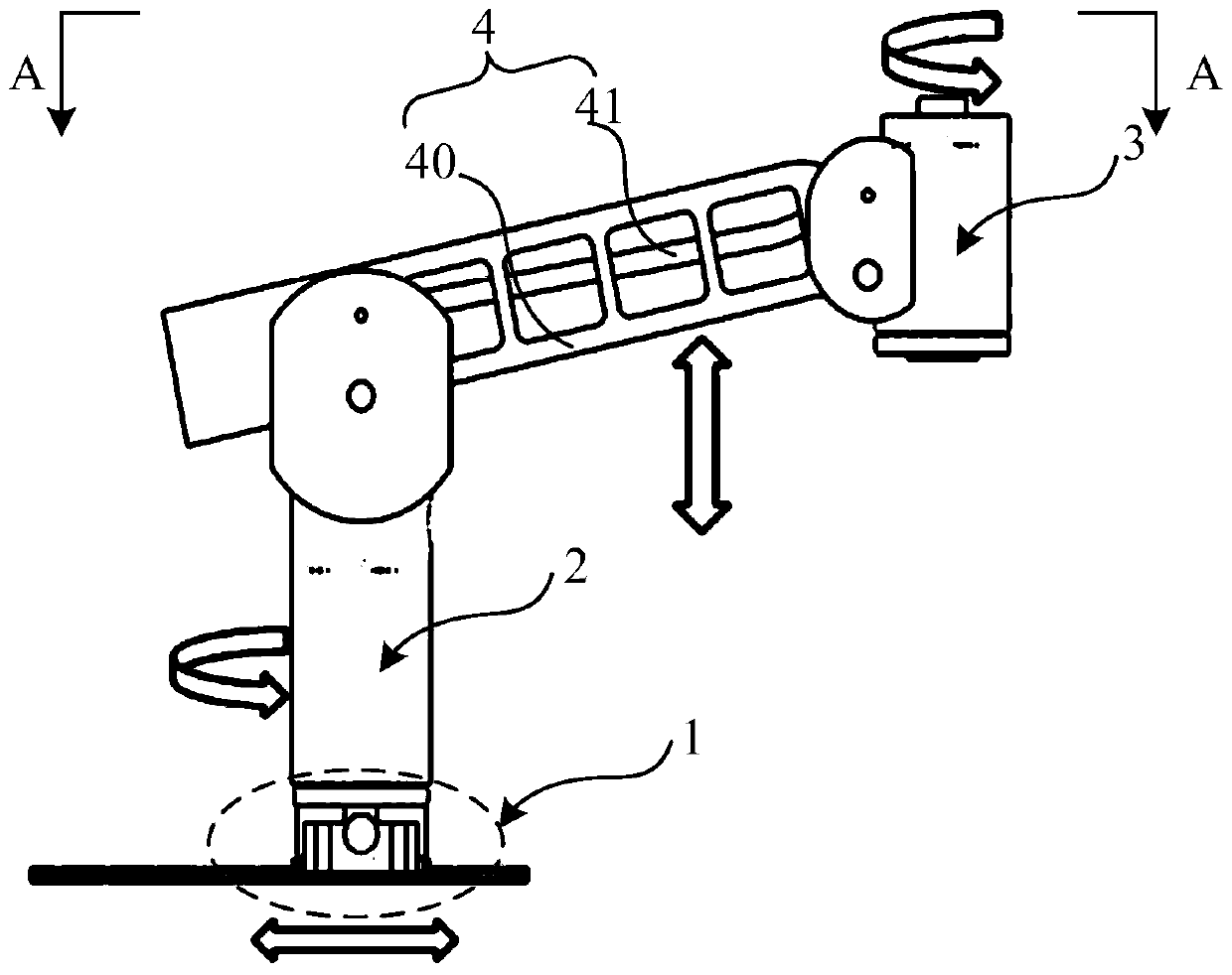
[0034] The mechanical arm proposed by the present invention will be further described in detail below with reference to the drawings and specific embodiments. Advantages and features of the present invention will be apparent from the following description and claims. It should be noted that all the drawings are in a very simplified form and use imprecise scales, and are only used to facilitate and clearly assist the purpose of illustrating the embodiments of the present invention.

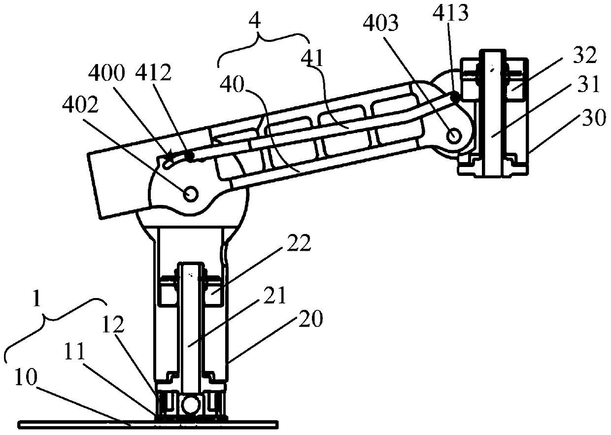
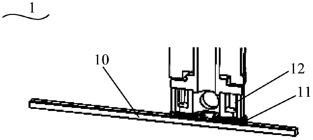
[0035] Please refer to figure 1 and figure 2 , figure 1 It is a front view of the structure of the mechanical arm in an embodiment of the present invention, figure 2 for figure 1 Sectional view along A-A direction. Such as figure 1 and figure 2As shown, the mechanical arm includes a sliding part 1, a first rotary joint 2, a swing part 4 and a second rotary joint 3 connected in sequence; the swing part 4 includes a connecting rod 40 and a pull rod 41; the connecting rod 40 The two ends of...


PUM


Abstract

The invention provides a mechanical arm. A slide part, a first rotating joint, a swing part and a second rotating joint are in sequential connection. The swing part comprises a connecting rod and a pull rod, two ends of each of the connecting rod and the pull rod are connected with the first rotating joint and the second rotating joint respectively to form four connection points, and sequential connection lines of the four connection points form a parallelogram. Therefore, the mechanical arm has a four-degree-of-freedom adjustment structure, and an operation direction of an implement arm mounted on the second rotating joint can be flexibly adjusted. Moreover, since a slider of a horizontal moving joint and a parallelogram mechanism are both positioned inside relevant parts, the mechanical arm is compact in integral structure, posture stability of the implement arm can be well kept without influences on integral rigidity of the implement arm, and flexibility of the mechanical arm is further improved.

Description

technical field [0001] The invention relates to the technical field of medical devices, in particular to a mechanical arm. Background technique [0002] Minimally invasive surgery refers to a surgical method in which surgery is performed inside the human cavity through endoscopes such as laparoscopy and thoracoscopic surgery. Compared with conventional surgery, minimally invasive surgery has the advantages of small wound, sufficient exposure, light injury, small postoperative reaction, quick recovery, and small scar. With the development of minimally invasive surgery and intelligent surgery, intelligent surgical equipment represented by robots has gained more and more applications in clinical surgery. Compared with traditional minimally invasive surgery, robotic minimally invasive surgery has the advantages of accuracy, reliability, less burden on doctors, and more dexterity. [0003] The robot realizes surgical operation through its mechanical arm. The surgical robotic ar...

Claims


Application Information

Patent Timeline
Patent Type & Authority Patents(China)
IPC IPC(8): A61B34/30A61B17/94B25J9/04B25J9/08B25J9/16
Inventor 何超李涛杨捷王常春
Owner SHANGHAI MICROPORT MEDBOT (GRP) CO LTD
Learn More