In-pipe Rubber bladder hydraulic forming device

A technology of hydroforming and rubber bladder, applied in the field of metal pressure processing, can solve the problems of waste of pipes, high requirements for end sealing of pipe fittings, long forming cycle, etc. The effect of the production process

Inactive Publication Date: 2016-01-13
NINGBO UNIVERSITY OF TECHNOLOGY
View PDF4 Cites 13 Cited by
  • Summary
  • Abstract
  • Description
  • Claims
  • Application Information

AI Technical Summary

Problems solved by technology

However, due to its technical characteristics, the existing hollow pipe hydroforming technology has some problems, which affect its popularization and application:
[0012] (1) Before the pipe fittings are formed, it is necessary to fill the liquid medium into the pipe fittings and empty the gas in the pipes. After forming, the liquid medium needs to be discharged from the inside of the pipe fittings, resulting in a long forming cycle and low production efficiency;
[0013] (2) The liquid medium is directly filled into the inside of the pipe fittings, resulting in high requirements for the sealing of the pipe ends, requiring special design of pipe end plugs, and the ends of pipe fittings usually require special processing, which wastes pipe materials;
[0014] (3) Since the liquid medium is directly in contact with the pipe fittings, the pipe fittings must go through a cleaning process after the liquid is discharged, which increases production costs;
[0015] (4) Traditional pipe fitting hydroforming equipment needs to realize the functions of large flow filling and discharge of liquid medium, precise pipe end sealing and recovery of leaking liquid medium, which leads to complex structure and high cost of equipment

Method used


Image

  • In-pipe Rubber bladder hydraulic forming device
  • In-pipe Rubber bladder hydraulic forming device
  • In-pipe Rubber bladder hydraulic forming device

Examples


Embodiment 1

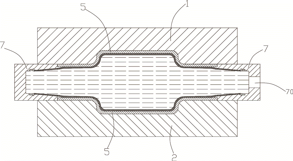
[0035] see figure 1 and figure 2 As shown, a specific embodiment of the rubber bag hydroforming device in the pipe of the present invention. A hydroforming device for a rubber bladder in a tube, comprising an upper mold 1 and a lower mold 2, the upper mold 1 is provided with an upper mold cavity 10, and the lower mold is provided with a lower mold cavity 20, after closing the upper mold cavity 10 and the lower mold cavity The cavities 20 are combined into a complete molding cavity. The shape of the cavity is determined by the shapes of different processed pipe fittings. A push rod 7 is arranged symmetrically between the upper die 1 and the lower die 2. On the push rod 7 A structure for medium injection is provided, which is an injection hole 70 for injecting the medium. The injection hole 70 is arranged on the push rod 7 on one side, and a rubber bag 3 is arranged between the push rods 7, and the rubber bag 3 The outer side is the pipe fitting 5 to be formed, and the two en...

Embodiment 2

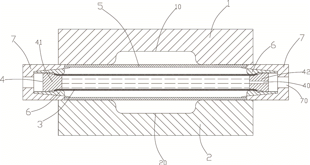
[0042] see image 3 and Figure 4 Shown, another specific embodiment of the hydroforming device of the rubber bag in the tube of the present invention. A hydroforming device for a rubber bladder in a tube, comprising an upper mold 1 and a lower mold 2, the upper mold 1 is provided with an upper mold cavity 10, and the lower mold is provided with a lower mold cavity 20, after closing the upper mold cavity 10 and the lower mold cavity The cavities 20 are combined into a complete molding cavity. The shape of the cavity is determined by the shapes of different processed pipe fittings. A push rod 7 is arranged symmetrically between the upper die 1 and the lower die 2. On the push rod 7 A structure for medium injection is provided, and the structure is an injection hole 70 for injecting medium. The injection hole 70 is arranged on one of the push rods 7 on one side, and a rubber bag 3 is arranged between the push rods 7 .

[0043] In the above technical solution, the two ends of t...


PUM


Abstract

The invention discloses an in-pipe rubber bladder hydraulic forming device. The in-pipe rubber bladder hydraulic forming device comprises an upper mould and a lower mould; an upper mould cavity is arranged in the upper mould; a lower mould cavity is arranged in the lower mould; and a complete forming mould cavity is spliced after the upper mould cavity and the lower mould cavity are closed; the shape of the mould cavity is determined by shapes of different machined pipes; push rods are symmetrically arranged between the upper mould and the lower mould; a structure used for injecting a medium is arranged on one push rod, and the structure is an injection hole used for injecting the medium; a pipe is arranged between the push rods; and a rubber bladder is arranged in the pipe in a sleeving manner, and the rubber bladder penetrates through two ends in the pipe. Compared with the prior art, the in-pipe rubber bladder hydraulic forming device is advantaged in that the high-pressure medium is injected into the rubber bladder; the rubber bladder expands to deform and cling to the inner wall of the pipe, and transfers pressure to the pipe, so that the pipe deforms and clings to the inner wall of the mould cavity to be finally formed into a part; the time for injecting or discharging the liquid medium during hydraulic forming of the pipe is effectively shortened; a subsequent cleaning process is omitted; and the advantages of low equipment requirement, high production efficiency, low production cost and the like are realized.

Description

technical field [0001] The invention belongs to the technical field of metal pressure processing, in particular to a hydroforming device for a rubber bag in a tube. Background technique [0002] Hydroforming, also known as internal high pressure forming, is a modern plastic processing technology that uses liquid as a pressure transmission medium and uses liquid high pressure to deform metal blanks into parts with complex three-dimensional shapes. The hydroforming of hollow pipes is an advanced plastic processing technology that makes the inside of the metal pipe withstand high-pressure fluid, forcing the pipe to bulge and deform outward to obtain the desired shape of the product. [0003] According to the geometric shape characteristics of formed pipe fittings and the process characteristics of hydroforming, the hydroforming of hollow pipe fittings can be divided into two categories: straight pipe forming with axial feed and pre-bent pipe forming without axial feed. During ...

Claims


Application Information

Patent Timeline
Patent Type & Authority Applications(China)
IPC IPC(8): B21D26/033
Inventor 周林
Owner NINGBO UNIVERSITY OF TECHNOLOGY
Why Eureka
Try Eureka