A large stroke steel coil lifting equipment

A technology with large strokes and steel coils, which is applied in the direction of hoisting devices and safety devices for lifting equipment, etc., can solve problems such as poor stability of oil cylinders, poor stability of pressure rods, and poor lifting heights, so as to reduce deformation of the frame and ensure good stress conditions , to counteract the effects of imbalance

Active Publication Date: 2017-06-06
SHANGHAI MEISHAN IND CIVIL ENG DESIGN & RES INST CO LTD
View PDF5 Cites 0 Cited by
  • Summary
  • Abstract
  • Description
  • Claims
  • Application Information

AI Technical Summary

Problems solved by technology

In order to solve the problem of lifting height difference in steel coil transportation, there are many kinds of lifting devices at home and abroad. These steel coil hoists all use oil cylinders to directly withstand the steel coil drag or lifting roller table to realize up and down movement, such as figure 1 , 2 As shown, the energy consumption
However, the stability of the pressure bar is poor, and the lifting stroke exceeds 4 meters for heavy equipment, and the stability of the oil cylinder is poor; therefore, how to provide a stable, safe and reliable operation for the long-stroke steel coil lifting requirements with the equipment lifting stroke greater than 4 meters. Steel coil hoisting equipment is a technical problem in this field

Method used


Image

  • A large stroke steel coil lifting equipment
  • A large stroke steel coil lifting equipment
  • A large stroke steel coil lifting equipment

Examples


Embodiment Construction

[0032] The present invention will be further described below in conjunction with the accompanying drawings and specific embodiments.

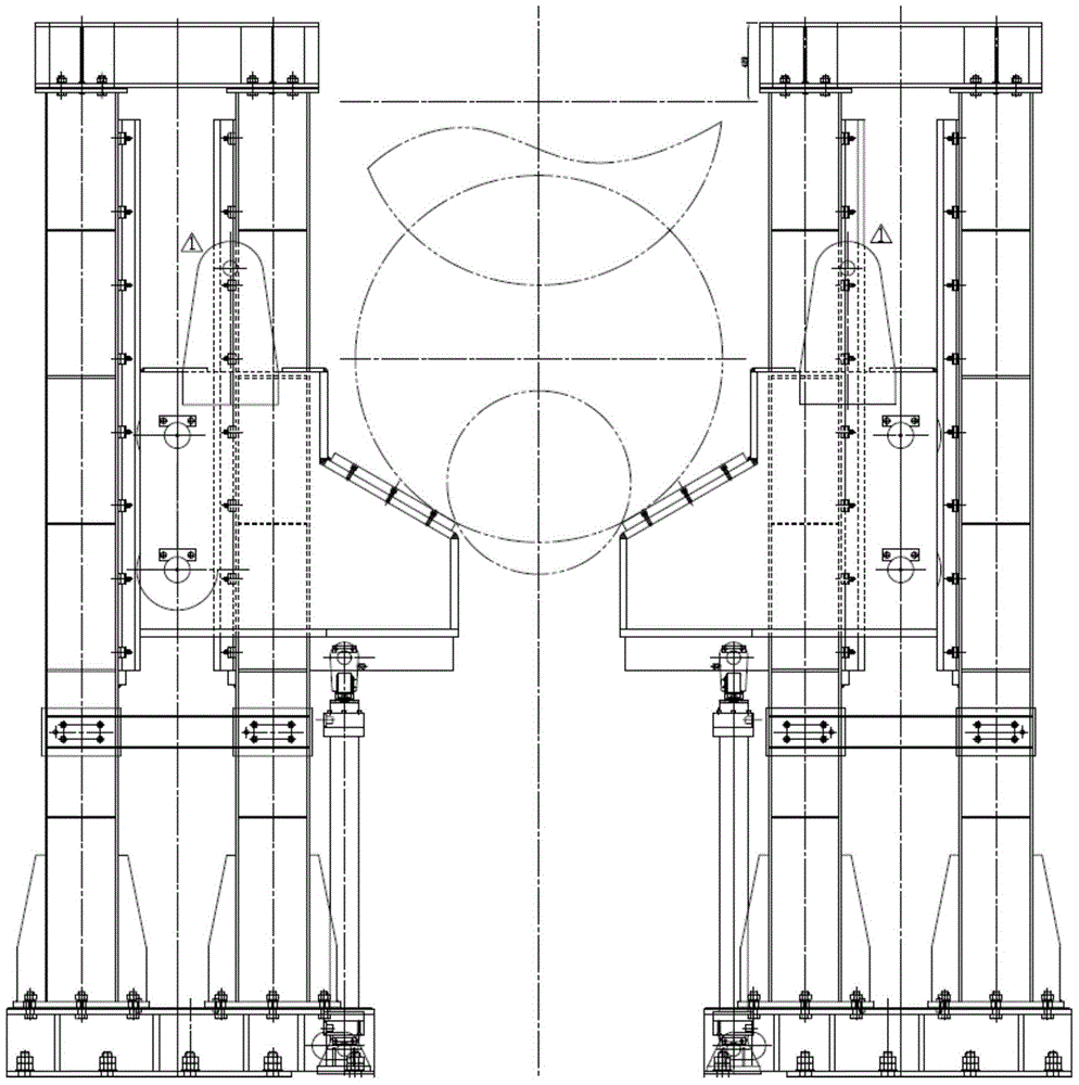
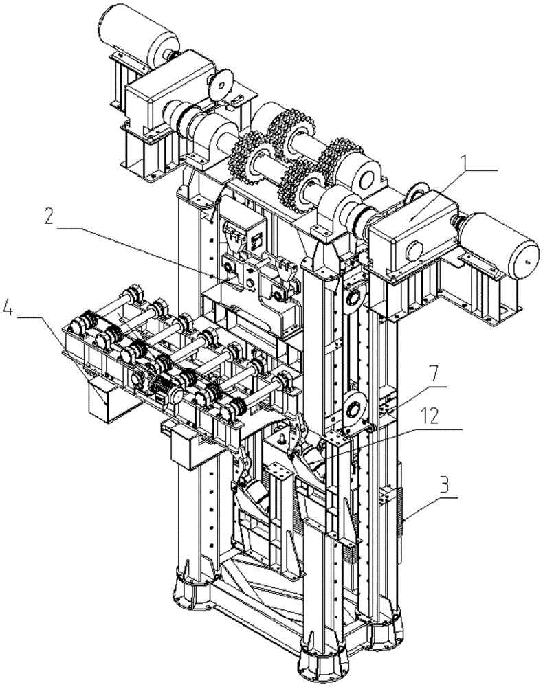
[0033] see Figure 3-Figure 9 , the present invention provides a kind of transport equipment for lifting and lowering metal strip volumes with a large stroke. 12. Automatic support device 5, frame 7, counterweight device 3, low support device 9, and horizontal support device 7a on the frame.

[0034] Working principle and structural features:

[0035] The driving device 1 of the present invention bears relatively large torque, so the driving device is placed on the foundation of the civil works, and the counter torque generated by the reducer and the motor is absorbed by the civil works;

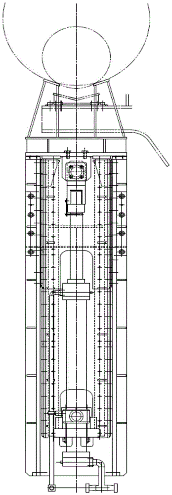
[0036] Pallets and steel coils are placed on the lifting roller table to move up and down with the lifting platform, and the lifting roller table is seated on the lifting platform, see Figure 7 ;

[0037] Adding a balance beam device 2 on the side of the...


PUM


Abstract

The invention relates to a large-stroke steel reel lifting device. The large-stroke steel reel lifting device comprises a rack, a drive device is arranged above a top base of the rack, and the top base is fixedly arranged on a civil engineering foundation. The drive device comprises a pair of motors. The motors drive a pair of chains to rotate through chain wheels respectively. The two side parts, located on the rack, of the chains are each connected with a balance beam device. One balance beam device is connected with a lifting table, and the other balance beam device is connected with a balance weight device. The lifting table is provided with a roller bed. The rack is provided with an automatic stop device implementing accurate stopping on the lifting table. The part, located on the side corresponding to the horizontal output roller bed, of the rack is provided with an overturning supporting device. The overturning supporting device is driven by an oil cylinder and drives a rocker arm to rotate. The rocker arm supports the side, close to the horizontal output roller bed, of the lifting table, and swinging of a steel reel during transverse conveying is reduced. Low-level supporting devices are arranged below the lifting table and carry out low-level supporting on the lifting table, and the lifting table is prevented from swinging.

Description

technical field [0001] The invention relates to a steel coil hoisting device, in particular to a steel coil hoisting device with a large stroke, and belongs to the technical field of steel coil hoisting equipment. Background technique [0002] In recent years, in the production and transportation of metal coils in the metallurgical industry, such as wide steel coils, the pallet circulation system has been widely used at home and abroad. Its characteristics are: during the transportation of steel coils, there is little useless mechanical work, that is, high efficiency; the structure is simple, the maintenance work and repair costs are relatively reduced; the construction investment and operation costs are relatively low. This type of tray circulation system can also be applied to steel strip coils with an external temperature of about 500°C to 800°C and a weight of 30t to 50t. In order to solve the problem of lifting height difference in steel coil transportation, there are ...

Claims


Application Information

Patent Timeline
Patent Type & Authority Patents(China)
IPC IPC(8): B66F3/44B66F17/00
Inventor 徐志杰尉鹏张小林陈建强
Owner SHANGHAI MEISHAN IND CIVIL ENG DESIGN & RES INST CO LTD
Why Eureka
Try Eureka