Electronic control multi-plate-type self-locking drive axle

A drive axle, multi-piece technology, applied in the field of machinery, can solve the problems of insufficient driving force to overcome driving resistance, accelerate parts wear, waste fuel, etc., achieve good locking and slip-limiting performance, avoid meshing stuck, improve The effect of driving ability

Inactive Publication Date: 2016-01-13
WENLING HUAXIN MACHINERY MFG
View PDF6 Cites 2 Cited by
  • Summary
  • Abstract
  • Description
  • Claims
  • Application Information

AI Technical Summary

Problems solved by technology

Ordinary differentials will seriously affect the passing ability when encountering extremely bad road conditions
For example, when the drive axle of a beach car or a farmer's car encounters muddy and very bad roads, the adhesion between the wheels on the muddy road and the road surface is small, and the road surface can only act on the axle shaft with a small reaction moment through the wheels. , so the torque distributed to this wheel by the differential is also small. Although the adhesion between the other driving wheel and the good road surface is relatively large, due to the characteristics of evenly distributed torque, this driving wheel can only be distributed to The same amount of torque as the slipping drive wheels, so that the driving force is no

Method used


Image

  • Electronic control multi-plate-type self-locking drive axle
  • Electronic control multi-plate-type self-locking drive axle
  • Electronic control multi-plate-type self-locking drive axle

Examples


Embodiment 1

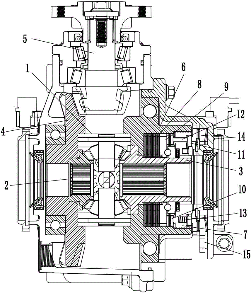
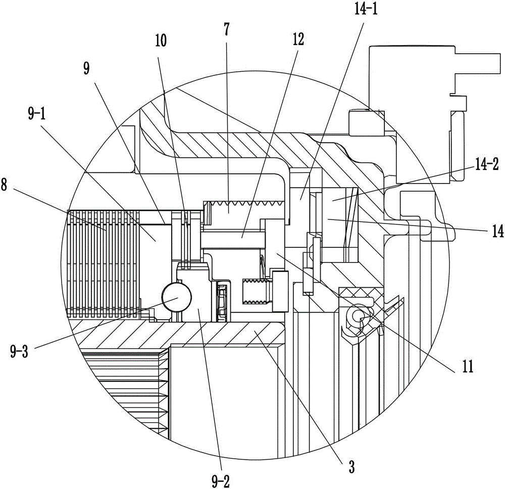
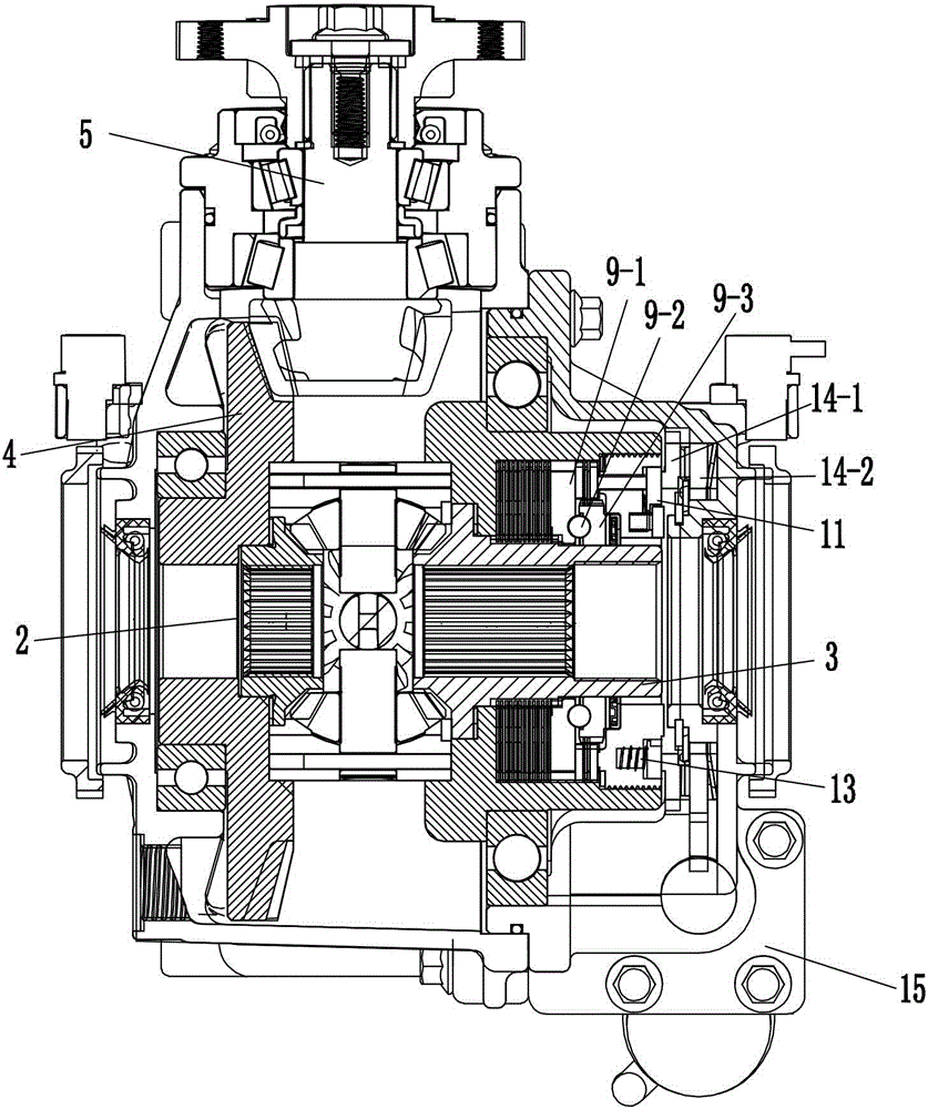
[0034] refer to figure 1 and figure 2As shown, an electronically controlled multi-piece self-locking drive axle described in this embodiment includes a drive axle box body and a drive axle box cover that is fastened on the right side of the drive axle box body. There is a first differential case 1, which is provided with a left side gear 2, a right side gear 3 and a planetary gear, and the first differential case 1 is fixedly connected with The transmission gear 4 is arranged coaxially with the left side shaft gear 2 , and the input gear 5 vertically meshing with the transmission gear 4 is also arranged in the drive axle casing. The right side gear 3 is covered with a cylindrical second differential case 6 and the right end of the second differential case 6 is sealed with a differential case cover 7, the second differential case 6 is connected to the drive The axle case covers are rotatably connected by bearings. The right side gear 3 is coaxially sleeved with a working fr...

Embodiment 2

[0046] refer to Figure 7 As shown, the structure of this embodiment is basically the same as that of Embodiment 1, the difference is that the drive mechanism adopts a push rod motor. Thereby under the state of locking and differential speed, be to rely on the expansion and contraction of electric control push rod motor to give the impetus of relative rotation of the 4th cam.

Embodiment 3

[0048] refer to Figure 8 As shown, an electronically controlled multi-piece self-locking drive axle described in this embodiment includes a drive axle box body and a drive axle box cover that is fastened on the right side of the drive axle box body. There is a first differential case 1, and the left side gear 2, the right side gear 3 and planetary gears are arranged in the first differential case 1, and the first differential case 1 is fixedly connected with the left side gear The side gear 2 is coaxially arranged with a transmission gear 4 , and an input gear 5 vertically meshing with the transmission gear 4 is also provided in the drive axle casing. The right side gear 3 is covered with a cylindrical second differential case 6 and the right end of the second differential case 6 is sealed with a differential case cover 7, the second differential case 6 is connected to the drive The axle case cover is rotatably connected by bearings. The right side gear 3 is coaxially sleev...


PUM


Abstract

The invention discloses an electronic control multi-plate-type self-locking drive axle. The electronic control multi-plate-type self-locking drive axle comprises a drive axle box with a first differential shell body and a drive axle box cover. The first differential shell body is internally provided with a left half axle gear, a right half axle gear, a planet gear and a transmitting gear. The drive axle box is internally provided with an input gear meshed with the transmitting gear. The right half axle gear is provided with a second differential shell body rotationally connected with the drive axle box cover and provided with a differential shell cover in a sealed manner. A work friction set is arranged between the right half axle gear and the second differential shell body, and a plane spherical-surface cam set abuts against the right end of the work friction set. A control friction set is arranged between the plane spherical-surface cam set and the second differential shell body. A pushing disc with a plurality of pushing rods and reset springs abuts against the right end of the differential shell cover, the pushing rods leftwards penetrate the differential shell cover and to be matched with the control friction set in an abutting manner, and the reset springs are arranged between the differential shell cover and the pushing disc. A plane cam set abuts against the right end of the pushing disc, and a driving mechanism for allowing the plane cam set to rotate in the circumferential direction is arranged at the outer end of the plane cam set. By means of the electronic control multi-plate-type self-locking drive axle of the structure, the sliding limiting effect is good, and the defect that locking can not be achieved easily during high-speed slipping is overcome.

Description

technical field [0001] The invention relates to the field of mechanical technology, in particular to an electronically controlled multi-chip self-locking drive axle. Background technique [0002] Inside the drive axle of the vehicle, the differential, as a device with power transmission and power distribution functions, can automatically adjust the speed of the inner and outer wheels during the turning process of the vehicle, so as to ensure that the outer wheels will not drag on the road and avoid tire damage. The wear and tear is intensified, so as to ensure the safety factor of the driving vehicle and improve the operating life of the reducer. Ordinary differentials will seriously affect the passing ability when encountering extremely bad road conditions. For example, when the drive axle of a beach car or a farmer's car encounters muddy and very bad roads, the adhesion between the wheels on the muddy road and the road surface is small, and the road surface can only act o...

Claims


Application Information

Patent Timeline
IPC IPC(8): F16H48/22F16H48/06F16H48/38B60K17/16
CPCF16H48/22B60K17/20F16H48/06F16H48/38
Inventor 张宇荣
Owner WENLING HUAXIN MACHINERY MFG
Why Eureka
Try Eureka