A spiral conveying heating and cooling equipment

A technology of cooling equipment and screw conveying, applied in the field of industrial heating furnaces, can solve the problems of large floor space, large power loss, low efficiency, etc., and achieve the effect of reducing floor space, improving efficiency and reducing power loss

Active Publication Date: 2018-02-27
XI AN AOJIE ELECTRIC HEATING EQUIP ENG CO LTD
View PDF4 Cites 0 Cited by
  • Summary
  • Abstract
  • Description
  • Claims
  • Application Information

AI Technical Summary

Problems solved by technology

[0002] At present, the workpiece transmission of the conveyor belt industrial heating furnace is all horizontal transmission. The equipment using this method has a large area, large power loss, and low efficiency.

Method used


Image

  • A spiral conveying heating and cooling equipment

Examples


Embodiment Construction

[0016] The present invention will be described in detail below in conjunction with the accompanying drawings and specific embodiments.

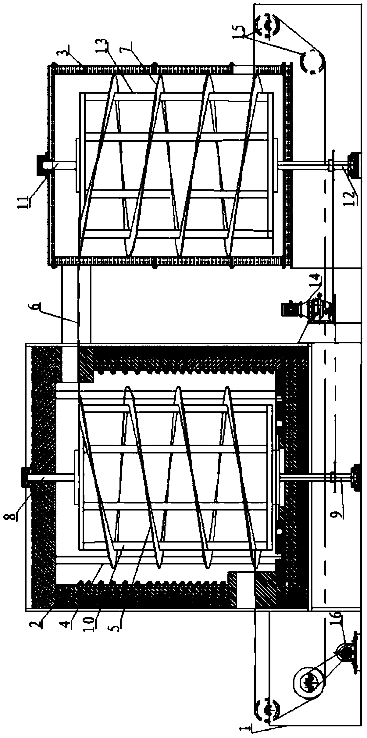
[0017] refer to figure 1 , is a structural schematic diagram of a spiral conveying heating and cooling equipment of the present invention; the spiral conveying heating and cooling equipment includes a general support frame 1, and a heating furnace 2 and a cooling furnace 3 connected to each other are arranged side by side on the general support frame 1 . The heating furnace 2 is composed of a furnace shell, a refractory layer, an insulating layer, and a heating element. The main function is to provide the workpiece with the temperature required for heat treatment and other heating. The heating furnace 2 and the cooling furnace 3 are connected by a conveyor belt transition device. A bracket 4 is arranged inside the heating furnace 2, and a first spiral support plate 5 of a spiral type is arranged on the support 4, and a conveyor belt 6 is a...


PUM


Abstract

The invention belongs to the technical field of industrial heating furnaces, and discloses a screw conveying type heating and cooling device. The device comprises a main supporting frame on which a heating furnace and a cooling furnace are arranged in parallel, wherein the heating furnace and the cooling furnace communicate with each other; a bracket is arranged in the heating furnace; a first screw type supporting plate is arranged on the bracket; a conveyor belt is arranged on the first screw type supporting plate in the screwing direction; a second screw type supporting plate is arranged in the cooling furnace; the conveyor belt in the cooling furnace is in the same direction as the second screw type supporting plate; a transmission mechanism for driving the conveyor belt to move is arranged on the main supporting frame; the conveyor belt runs through the inner parts of the heating furnace and the cooling furnace and forms a loop through the transmission mechanism. With the adoption of the screw conveying type heating and cooling device, the energy can be saved, the high efficiency can be achieved, and the area for equipment can be saved. The productivity can be greatly increased under the same used area and energy consumption.

Description

technical field [0001] The invention belongs to the technical field of industrial heating furnaces, in particular to a spiral conveying heating and cooling equipment. Background technique [0002] At present, the workpiece transmission of the conveyor belt industrial heating furnace is all horizontal transmission. The equipment using this method has a large area, large power loss, and low efficiency. Contents of the invention [0003] The object of the present invention is to provide a spiral conveying heating and cooling equipment, which is energy-saving and efficient and saves the occupied area of ​​the equipment. Under the same floor area and energy consumption, the production capacity can be greatly increased. [0004] In order to achieve the above object, the present invention adopts the following technical solutions to achieve. [0005] A spiral conveying type heating and cooling equipment, characterized in that: it includes a general support frame, and a heating f...

Claims


Application Information

Patent Timeline
Patent Type & Authority Patents(China)
IPC IPC(8): C21D1/00F27B19/04F27D3/00
Inventor 扈杰
Owner XI AN AOJIE ELECTRIC HEATING EQUIP ENG CO LTD
Why Eureka
Try Eureka