
A Method for Measuring Relative Outer Orientation Elements of Arbitrary Ground Photographic Image Pairs Without Known Image Control Points

A technology of azimuth elements and measurement methods, applied in photogrammetry/video metrology, measuring devices, surveying and navigation, etc., to achieve the effect of easy operation

Active Publication Date: 2017-05-03
BEIJING FORESTRY UNIVERSITY
View PDF2 Cites 0 Cited by
  • Summary
  • Abstract
  • Description
  • Claims
  • Application Information

AI Technical Summary

Problems solved by technology

[0009] In order to overcome the deficiencies and limitations of existing photogrammetry in determining external orientation elements, and to apply photogrammetry technology to a greater extent and in a wider range, the purpose of the present invention is to provide a ground arbitrary photographic image pair without known image control points. Determination method of relative outer orientation elements

Method used


Image

  • A Method for Measuring Relative Outer Orientation Elements of Arbitrary Ground Photographic Image Pairs Without Known Image Control Points
  • A Method for Measuring Relative Outer Orientation Elements of Arbitrary Ground Photographic Image Pairs Without Known Image Control Points
  • A Method for Measuring Relative Outer Orientation Elements of Arbitrary Ground Photographic Image Pairs Without Known Image Control Points

Examples


Embodiment Construction

[0023] Using no known control points to measure the relative outer orientation elements of the image pair has greatly improved both in theory and operation, and provides a new theory and method for the determination of the outer orientation elements of the camera, specifically:

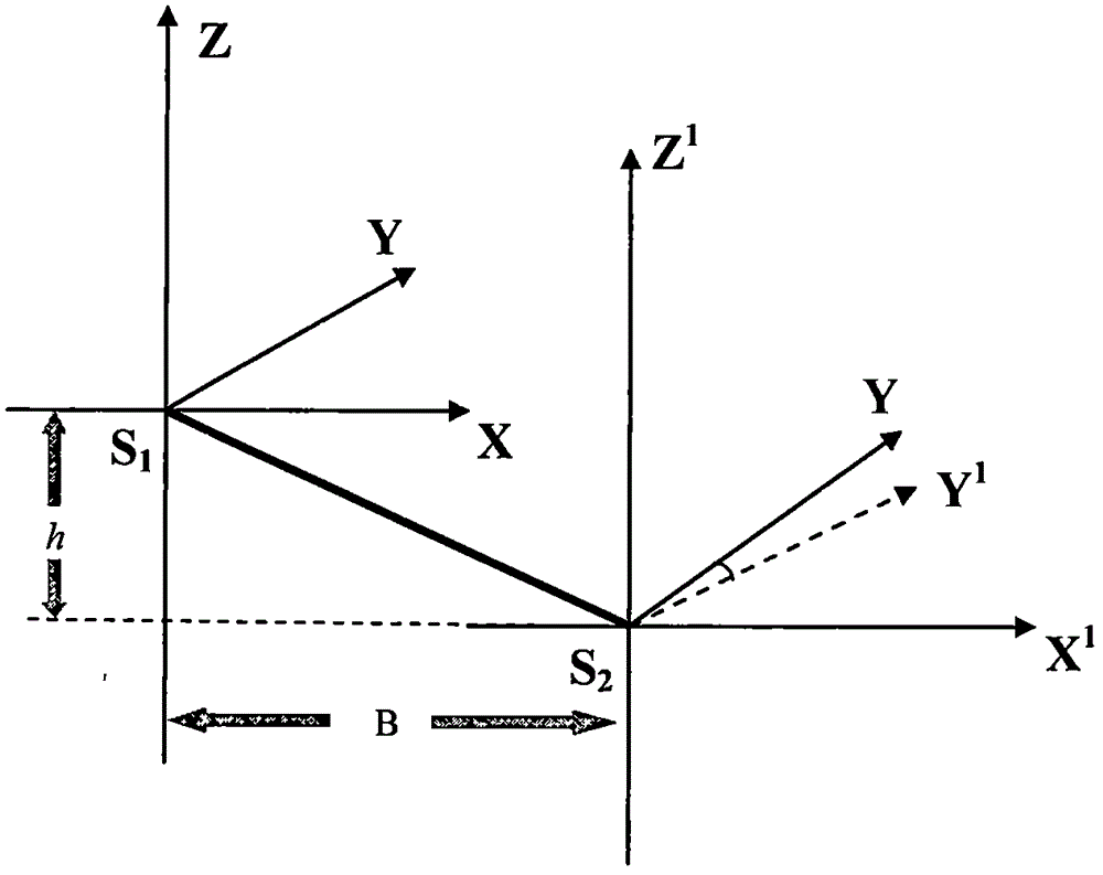
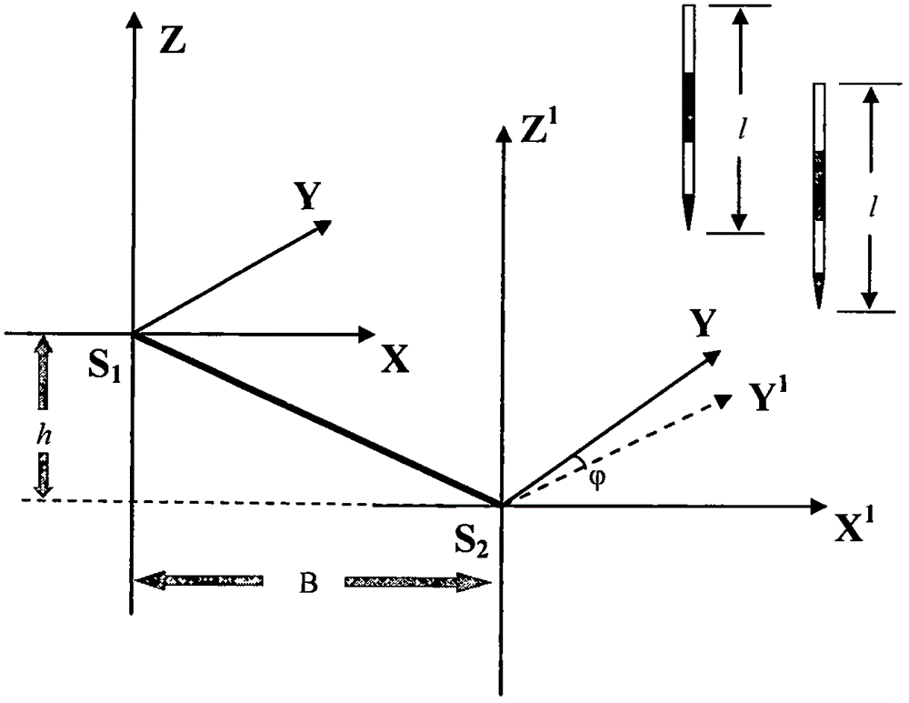
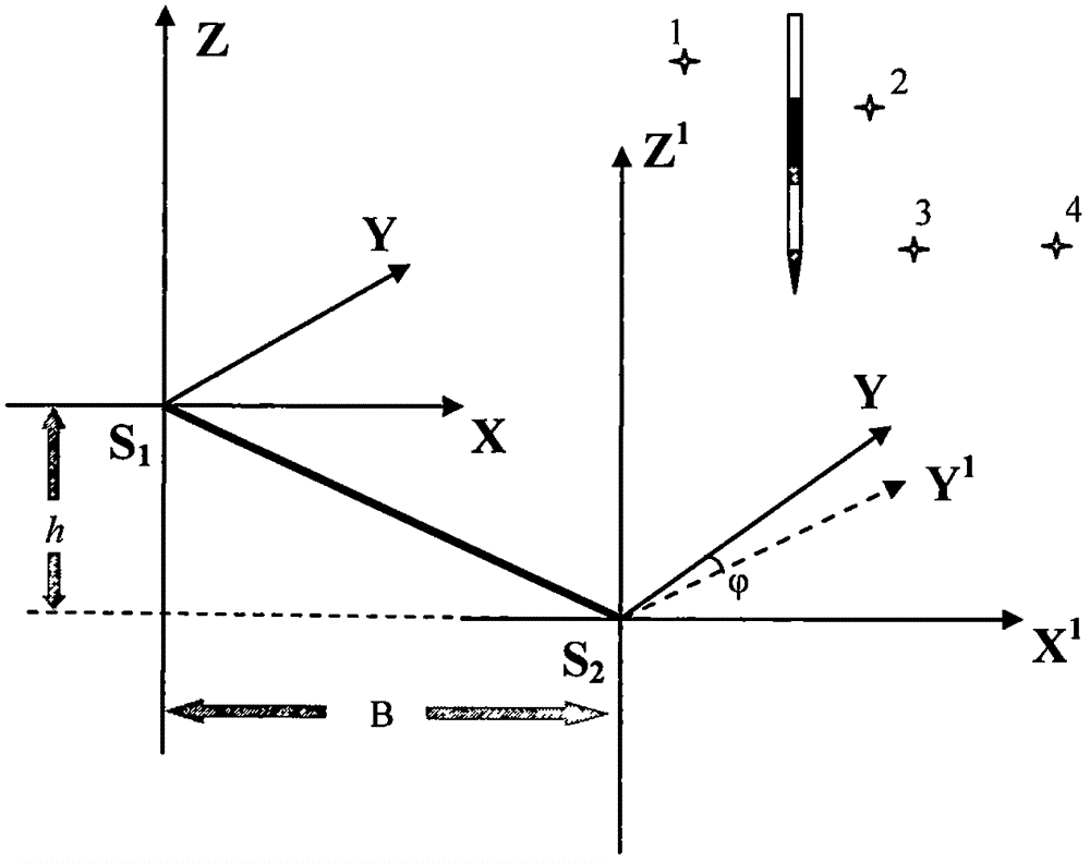
[0024] 1)(1) if figure 1 As shown in , two observation points S1 and S2 are selected on the ground of the area to be measured, and the camera is used to take upright photography of the object to be measured, so as to ensure that the object to be measured is clearly imaged on the photographic photo, so as to obtain the required stereoscopic image pair;

[0025] (2) Based on one of the photos, that is, the rotation matrix R=E, using the mathematical model ① and mathematical model② Establish the model equations of the stereo pair of the target object to be measured respectively, where (X i , Y i ,Z i ) is the object space coordinate of any point in space, λ i , lambda i 'is the scaling factor, R ...


PUM


Abstract

The invention discloses a measurement method for relative exterior orientation elements by using an arbitrary photographic image pair of ground without any known photogrammetric control point. The measurement method provided by the invention comprises the following steps: directed at a mark-free condition, selecting two observation points near a to-be-measured area by utilizing arbitrary photogrammetric measurement technology, subjecting a to-be-measured object to nearly horizontal normal case photographing with a fixed-focus camera so as to obtain stereoscopic image pairs, and calculating the relative exterior orientation elements of the camera by utilizing a collinearity equation mathematic model and more than 6 corresponding image points; vertically placing two fixed-length sighting rods near the to-be-measured object, respectively photographing the two observation points, then calculating coordinates of object space of a rod endpoint through the lengths of the fixed-length sighting rods, and calculating the relative exterior orientation elements of the camera by utilizing a mathematic model and point coordinates; and vertically placing a fixed-length sighting rod near the to-be-measure object, then selecting more than 3 known points in a photographed image and calculating the relative exterior orientation elements of the camera during photographing by utilizing the length of the fixed-length sighting rod and the three known points.

Description

[0001] 1. Technical field [0002] The invention relates to a method for measuring relative outer orientation elements, in particular to a method for measuring relative outer orientation elements of any photographic image pair on the ground without known image control points. [0003] 2. Technical Background [0004] With the rapid development of photogrammetry and the continuous extension of the application field, more and more problems involve the solution of photogrammetry, and the determination of the external orientation elements is the key to the solution of photogrammetry. In the current application of photogrammetry , calculating the outer orientation elements has always been a complicated problem, and the deficiencies and limitations in it are also obvious, which brings great trouble and inconvenience to the post-processing of photogrammetry: [0005] ① The external orientation elements vary with the position and attitude of the photographic camera, and it is difficult...

Claims


Application Information

Patent Timeline
Patent Type & Authority Patents(China)
IPC IPC(8): G01C11/00G01C11/08
CPCG01C11/00G01C11/08
Inventor 冯仲科刘金成邱梓轩
Owner BEIJING FORESTRY UNIVERSITY
Learn More