Substrate structure

A technology for substrates and bonding pads, applied in the direction of static indicators, etc., can solve problems such as bonding pad corrosion, equipment failure, control signal transmission problems, etc., achieve good bonding adhesion, avoid corrosion, and block moisture or oxygen from entering.

Active Publication Date: 2019-02-12
INNOLUX CORP
View PDF4 Cites 0 Cited by
  • Summary
  • Abstract
  • Description
  • Claims
  • Application Information

AI Technical Summary

Problems solved by technology

[0004] However, in the prior art, the conductive adhesive used to bond the bonding pad to the control circuit board is simply covered on the bonding pad. After a long period of use, the conductive adhesive may not be able to effectively block moisture or oxygen from entering and contact the bonding pad. , resulting in the corrosion of the bonding pads, causing problems in the transmission of control signals, and causing equipment failures

Method used


Image

  • Substrate structure
  • Substrate structure
  • Substrate structure

Examples


Embodiment Construction

[0039] The structure of the substrate according to the preferred embodiment of the present invention will be described below with reference to related drawings, wherein the same components will be described with the same reference symbols. The illustrations of all the implementation aspects of the present invention are only schematic representations, and do not represent real dimensions and proportions.

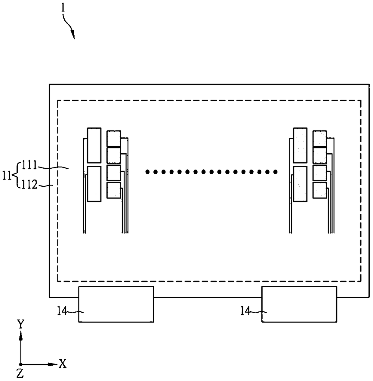
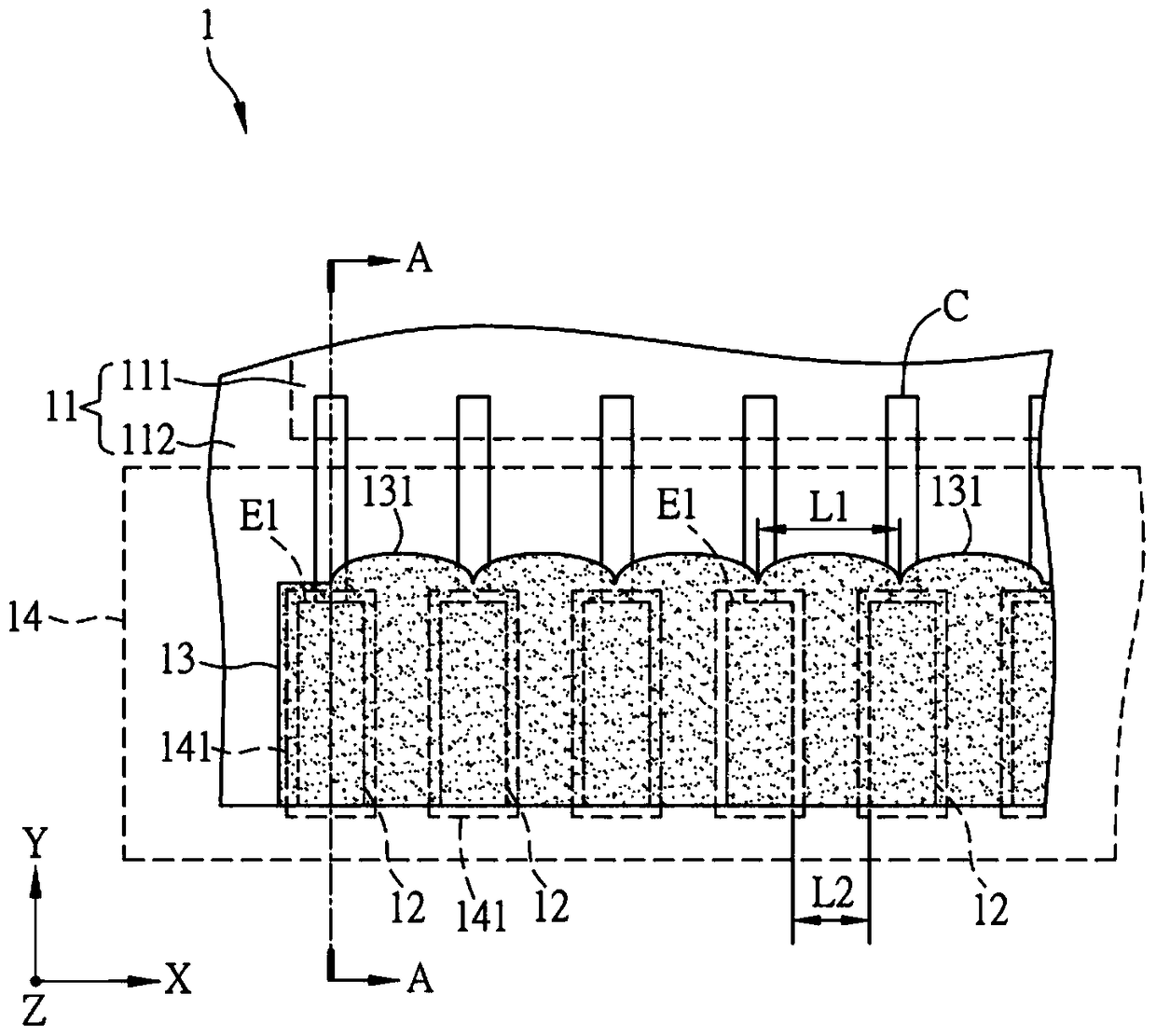
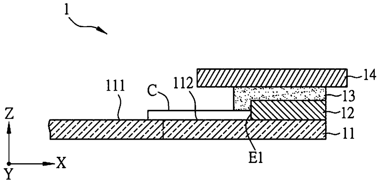
[0040] Please refer to Figure 1A to Figure 1C As shown, among them, Figure 1A It is a schematic top view of a substrate structure 1 in a preferred embodiment of the present invention, Figure 1B for Figure 1A A partially enlarged schematic diagram of the substrate structure 1, while Figure 1C for Figure 1B , the schematic cross-sectional view of line A-A.

[0041] The substrate structure 1 includes a first substrate 11 , a plurality of first bonding pads 12 and a bonding layer 13 . In addition, the substrate structure 1 of this embodiment further includes a second su...


PUM


Abstract

A base plate structure comprises a first base plate, a plurality of first bonding pads and a first bonding layer, wherein the first base plate is provided with an element configuration area and a periphery area; the periphery area is adjacently set on the outer periphery of the element configuration area; the first bonding pads are set on the periphery area at interval; a clearance is set between two adjacent first bonding pads; the bonding layer is set on the first base plate and the bonding layer covers the first bonding pads and the clearances; and the bonding layer adjacent to the element configuration area is provided with a plurality of first arc-shaped edges. After the base plate structure is used for a long time, the bonding layer can effectively prevent moisture or oxygen from entering, thus the first bonding pads are avoided from being rusted and the bonding adhesiveness is better.

Description

technical field [0001] The present invention relates to a substrate structure, in particular to a substrate structure capable of being electrically connected to a circuit board. Background technique [0002] With the advancement of technology, flat panel display devices have been widely used in various fields, such as liquid crystal display devices, which have gradually replaced traditional cathode ray tube display devices due to their superior characteristics such as light and thin body, low power consumption and no radiation. And it is applied to many kinds of electronic products, such as mobile phones, portable multimedia devices, notebook computers or tablet computers, and so on. [0003] Wherein, taking the control of the components on the thin film transistor substrate as an example, in order to transmit the control signal from the external control circuit board to the components on the glass substrate, a bonding pad (bonding pads) is generally arranged at the edge of ...

Claims


Application Information

Patent Timeline
Patent Type & Authority Patents(China)
IPC IPC(8): G02F1/133
Inventor 刘佳秤张嘉雄汪安昌王兆祥陈扬证
Owner INNOLUX CORP
Why Eureka
Try Eureka