an oil-filled motor

An oil motor and barrel technology, applied in electrical components, electromechanical devices, electric components, etc., can solve the problems of complex procedures, affecting air cavity sealing, difficult to fix bolts, etc., and achieve the effect of simplifying procedures

Active Publication Date: 2017-09-22
浙江东音科技有限公司
View PDF5 Cites 0 Cited by
  • Summary
  • Abstract
  • Description
  • Claims
  • Application Information

AI Technical Summary

Problems solved by technology

like figure 1 As shown, the existing oil-filled motor is composed of an organic barrel 1, an upper bearing seat 2, and an upper cap 3. An oil cavity is formed in the barrel, which needs to be filled with a certain amount of lubricating oil, and an air cavity is formed in the upper cap 3. Electronic components are installed, so the air cavity and the oil cavity need to be sealed independently to prevent the lubricating oil in the oil cavity from entering the air cavity and damaging the electronic components, and the cables in the oil cavity need to enter the air cavity, so if figure 2 As shown, an outlet hole 7 is opened on the upper bearing seat 2, and an outlet sheath 6 is arranged in the outlet hole 7, and the outlet sheath 6 is locked and fixed by the sealing bolt 71. After the oil-filled motor is assembled, the oil The airtightness of the chamber and the air chamber is tested. At this time, it is necessary to open holes for the barrel 1 and the upper cap 3, and then inject high-pressure gas into the air chamber and the oil chamber one by one for testing. After the test, the opened holes need to be sealed. , because the upper cap 3 is usually made of stainless steel sheets, it is difficult to fix the bolts, so it is necessary to weld the nut at the opening of the upper cap, and then seal it through the bolt and the gasket, not only two operations are required to detect the air cavity and oil during the test At the same time, the opening and resealing of the upper cap will complicate the process and increase the cost, and will affect the airtightness of the air cavity during later use

Method used


Image

  • an oil-filled motor
  • an oil-filled motor
  • an oil-filled motor

Examples


Embodiment 1

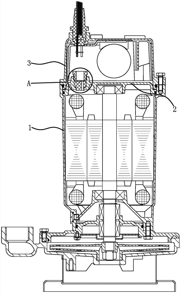
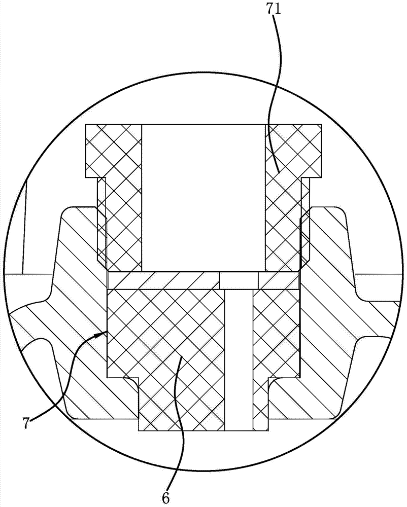
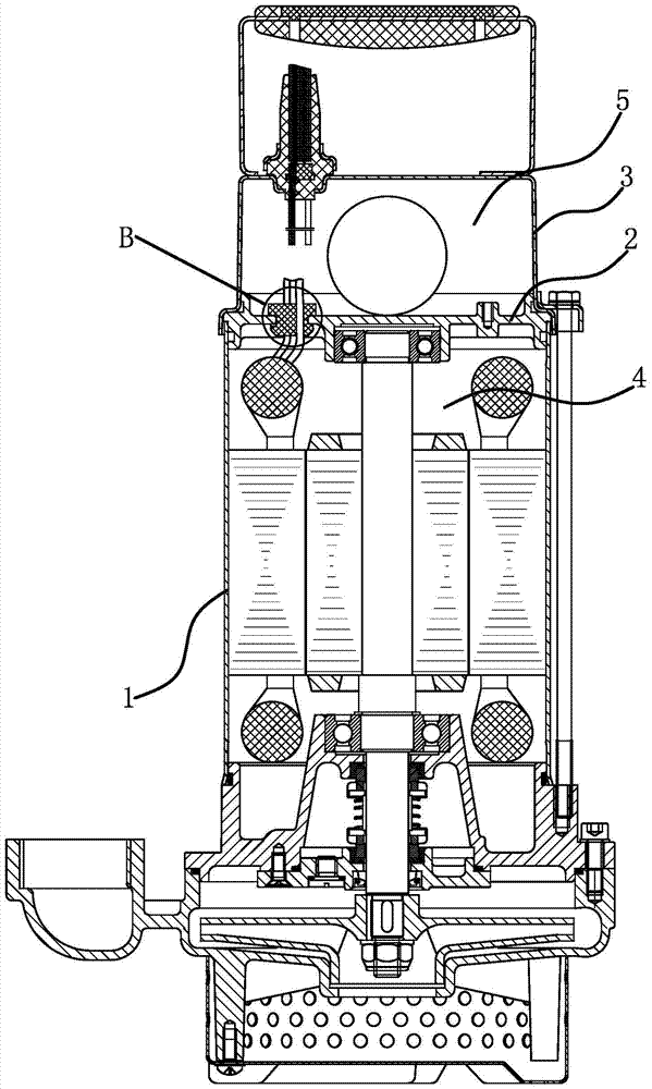
[0027] Such as image 3 , Figure 4As shown, an oil-filled motor includes a machine barrel 1, an upper bearing seat 2 and an upper cap 3, one end of the machine barrel 1 is closed, the upper bearing seat 2 is sealed and fixedly connected to the other end of the machine barrel 1, and the upper cap 3 is sealed and fixed. Connected to the upper bearing seat 2, an oil chamber 4 is formed between the upper bearing seat 2 and the barrel 1, which is used to install motor shafts, rotors, stators and other components. At the same time, a certain amount of lubricating oil needs to be filled in the oil chamber 4 for For cooling and lubrication, an air chamber 5 is formed between the upper bearing seat 2 and the upper cap 3, which is used to install electronic components, control panels and other components. The upper bearing seat 2 is provided with a detection hole 21 connecting the oil chamber 4 and the air chamber 5 A cylindrical and elastic outlet sheath 6 is fixedly inserted into th...

Embodiment 2

[0031] The structure of the oil-filled motor is basically the same as that of Embodiment 1, the difference is that Figure 6 As shown, the introduction structure includes an introduction tapered surface 622, the introduction tapered surface 622 is located at the end face edge of the limit portion 62 and the upper bearing seat 2, and the smaller end edge of the introduction tapered surface 622 is in contact with the side surface of the upper bearing seat 2 In contact with each other, the gas in the oil chamber 4 can squeeze the limit part 62 at the introduction tapered surface 622, so that a gap is formed between the end surface of the limit part 62 and the side surface of the upper bearing seat 2, and the gas enters the gap and further squeezes the radial direction. Extrude the outlet sheath 6.


PUM


Abstract

The invention provides an oil-filled motor, belonging to the technical field of motor equipment. The oil-filled motor solves the problems that a hole needs to be formed in an upper cap and the operation is tedious when the existing oil-filled motor is subjected to airtightness detection. The oil-filled motor comprises a motor cylinder, an upper bearing pedestal and an upper cap, wherein the upper bearing pedestal is fixed connected to the end part of the motor cylinder, the upper cap is fixed connected on the upper bearing pedestal, a detection hole is formed on the upper bearing pedestal, an outgoing wire sheath is fixedly inserted in the detection hole, a wire passing hole is formed in the outgoing wire sheath along the axial direction, one end of the outgoing wire sheath extends into an oil cavity, a limiting part is arranged on the outer circumferential wall of the end extending into the oil cavity, and the end, extending into the oil cavity, of the outgoing wire sheath is further provided with a leading-in structure which can guide a gas in the oil cavity to extrude the outgoing wire sheath and passes through a space between the outer circumferential wall of the outgoing wire sheath and the hole wall of the detection hole. When the oil-filled motor provided by the invention is subjected to airtightness detection, the hole does not need be formed in the upper cap, and the airtightness of the gas cavity and the oil cavity can be detected simulatenously in a single test.

Description

technical field [0001] The invention belongs to the technical field of motor equipment, and relates to an oil-filled motor. Background technique [0002] Oil-filled motors are mainly used to drive submersible pumps, and are widely used in agriculture, industrial and mining enterprises, coal mine drainage, urban water supply, and groundwater extraction in plateau areas. weakly corrosive water. Such as figure 1 As shown, the existing oil-filled motor is composed of an organic barrel 1, an upper bearing seat 2, and an upper cap 3. An oil cavity is formed in the barrel, which needs to be filled with a certain amount of lubricating oil, and an air cavity is formed in the upper cap 3. Electronic components are installed, so the air cavity and the oil cavity need to be sealed independently to prevent the lubricating oil in the oil cavity from entering the air cavity and damaging the electronic components, and the cables in the oil cavity need to enter the air cavity, so if figu...

Claims


Application Information

Patent Timeline
Patent Type & Authority Patents(China)
IPC IPC(8): H02K5/132G01M3/32
Inventor 方秀宝吴刚米勇黄中波范卫兵
Owner 浙江东音科技有限公司
Why Eureka
Try Eureka