End effector assisting in clamping endoscope in minimally invasive surgery

An end effector and minimally invasive surgery technology, applied in the field of minimally invasive surgery medical equipment, can solve the problems of complex structure, easy to produce movement interference, heavy weight of clamping endoscope, etc.

Active Publication Date: 2016-01-20
吉林省金博弘智能科技有限责任公司
View PDF16 Cites 18 Cited by
  • Summary
  • Abstract
  • Description
  • Claims
  • Application Information

AI Technical Summary

Problems solved by technology

[0004] In order to solve the problems that the device for holding the endoscope in the existing surgical operation is heavy, complex in structure, prone to motion interference during the swing process, and exerts force on the patient's surgical incision, the present invention further proposes an auxiliary device for minimally invasive surgery. End effector for clamping endoscope

Method used


Image

  • End effector assisting in clamping endoscope in minimally invasive surgery
  • End effector assisting in clamping endoscope in minimally invasive surgery
  • End effector assisting in clamping endoscope in minimally invasive surgery

Examples


specific Embodiment approach 1

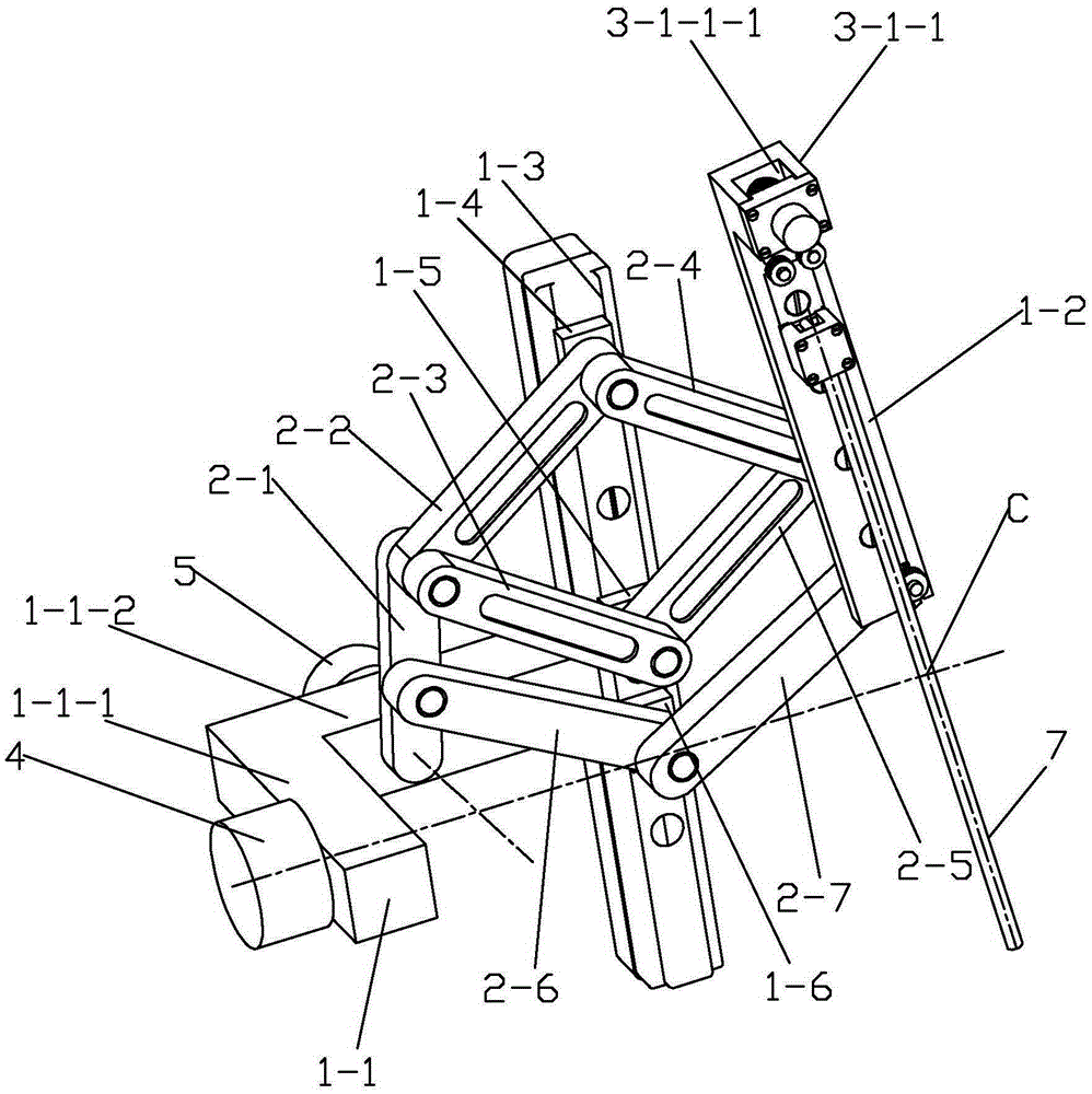
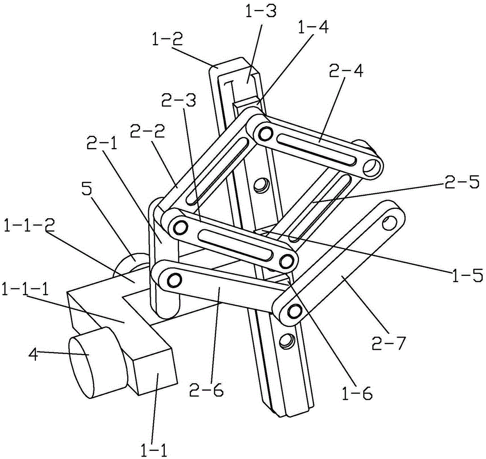
[0022] Specific implementation mode one: combine figure 1 , figure 2 , image 3 , Figure 4 , Figure 5 , Image 6 , Figure 7 , Figure 8 , Figure 9 with Figure 10 This embodiment is described. An end effector for clamping an endoscope in assisting minimally invasive surgery in this embodiment includes a base, a symmetrical body, an end telescopic body, a first reducer 4, a second reducer 5 and a second reducer. Three reducers 6, the base includes a frame 1-1, a column 1-2, a first linear guide 1-3, a first slider 1-4, a second slider 1-5 and a third slider 1-6, the frame 1-1 is L-shaped and placed horizontally, the column 1-2 is vertically installed on the end face of the long side 1-1-2 of the frame 1-1, and the end face of the column 1-2 along its length direction The first linear guide rail 1-3 is provided, and the first slider 1-4, the second slider 1-5 and the third slider 1-6 are sequentially arranged in the first linear guide rail 1-3 from top to bottom , t...

specific Embodiment approach 2

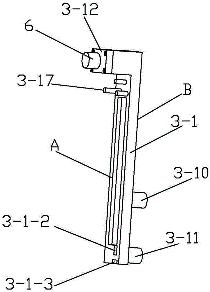
[0027] Specific implementation mode two: combination figure 1 with Figure 5 To illustrate this embodiment, a protrusion 3-1-1 is provided on the end face A of the telescopic body 3-1 in this embodiment near the first guide wheel 3-6, and the upper end face of the protrusion 3-1-1 A mounting groove 3-1-1-1 is provided along its height direction, and the mounting groove 3-1-1-1 is arranged through the length direction of the telescopic body 1, and the ball spline pair 3-3 is arranged in the mounting groove 3-1 -1-1 within. Such arrangement ensures that the ball spline pair 3-3 and the endoscope tool holder 3-4 are on the same plane. Other compositions and connections are the same as those in the first embodiment.

specific Embodiment approach 3

[0028] Specific implementation mode three: combination Figure 4 with Figure 5 Describe this embodiment, the ball spline pair 3-3 in this embodiment includes a ball spline shaft 3-3-1, an outer cylinder 3-3-2, a connecting key 3-3-3 and a wire cylinder 3-3- 4. One end of the ball spline shaft 3-3-1 is vertically inserted into the installation groove 3-1-1-1, and the other end of the ball spline shaft 3-3-1 is connected to the third reducer 6 through the coupling The outer wall of the ball spline shaft 3-3-1 is fixed with an outer cylinder 3-3-2, and the outer wall of the outer cylinder 3-3-2 is covered with a wire cylinder 3-3-4. The drum 3-3-2 is connected with the wire drum 3-3-4 through the connection key 3-3-3, and the steel wire 3-5 is wound on the wire drum 3-3-4. In this way, when the third speed reducer 6 drives the ball spline shaft 3-3-1 to rotate, the wire drum 3-3-4 can move linearly up and down along the axis of the ball spline shaft 3-3-1, Ensure that the in ...


PUM


Abstract

The invention relates to an end effector assisting in clamping an endoscope in minimally invasive surgery. The end effector aims at solving the problems that in existing surgery, a device for clamping an endoscope is high in weight, complex in structure and prone to generating movement interference in the swinging process, and acting force applied to a surgical incision of a patient exists. According to the end effector, a second connecting rod, a third connecting rod, a fourth connecting rod and a fifth connecting rod are equal in length, after the second connecting rod, the third connecting rod, the fourth connecting rod and the fifth connecting rod are connected, a rhombus is formed, the rhombus is symmetrically arranged with the center line of a first linear guide rail in the length direction as the symmetry axis, one end of a sixth connecting rod is hinged to the middle of the first connecting rod, the other end of the sixth connecting rod is hinged to one end of a seventh connecting rod and then fixed to a third slide block, the other end of the seventh connecting rod is arranged on a tail end telescopic body in a hinged mode, the sixth connecting rod and the seventh connecting rod are equal in length, and the sixth connecting rod and the seventh connecting rod are symmetrically arranged with the center line of the first linear guide rail in the length direction as the symmetry axis. The end effector is applied to the technical field of minimally invasive surgery medical equipment.

Description

technical field [0001] The invention relates to the technical field of medical equipment for minimally invasive surgery, in particular to an end effector for assisting in minimally invasive surgery for clamping an endoscope. Background technique [0002] In traditional minimally invasive surgery, an assistant is required to hold the endoscope to provide visual guidance for the attending doctor. This method of operation results in poor hand-eye coordination of the doctor and the fatigue of the assistant who holds the endoscope for a long time. Stablize. In order to solve this problem, in recent years, robot technology has been widely used in minimally invasive surgery. The robot-assisted minimally invasive surgery developed from this uses the end effector of the surgical robot to replace the doctor's control of the surgical instrument and the assistant's control of the endoscope. The doctor can control the movement of the end effector to complete the transformation of the fi...

Claims


Application Information

Patent Timeline
Patent Type & Authority Applications(China)
IPC IPC(8): A61B34/30A61B17/00
Inventor 冯美董光友付宜利赵继
Owner 吉林省金博弘智能科技有限责任公司
Why Eureka
Try Eureka