Mixing tank with air blowing device for lubricating oil production system

A technology of production system and preparation tank, which is applied in the direction of lubricating composition, dissolution, mixer, etc., and can solve problems such as inability to melt, grease layering, and poor anti-wear effect

Inactive Publication Date: 2016-01-20
华文蔚
View PDF3 Cites 5 Cited by
  • Summary
  • Abstract
  • Description
  • Claims
  • Application Information

AI Technical Summary

Problems solved by technology

[0002] Due to mechanical stirring, it is impossible to fully melt with other additives added, so there are sometimes phenomena such as grease stratification and poor anti-wear effect.

Method used


Image

  • Mixing tank with air blowing device for lubricating oil production system

Examples


Embodiment 1

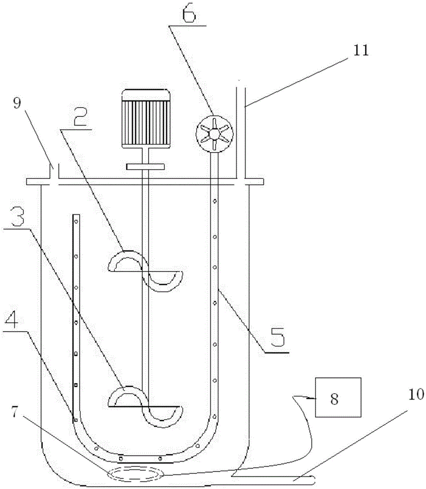
[0006] Embodiment 1: with reference to attached figure 1 . A special preparation tank for the lubricating oil production system. The preparation tank is equipped with a spiral agitator 2 and 3 and a wind agitator. The wind agitator is composed of a blowing pipe 5 and a fan 6. There are multiple blowing nozzles on the wall of the blowing pipe 4. The air inlet of the blower pipe is connected with the air outlet of the blower fan 6 . The blowing pipe 5 is H-shaped, and a plurality of blowing nozzles 4 are arranged on the opposite surface of the H-shaped pipe wall, and the horizontal pipe in the H-shaped pipe is located on one side of the stirring device. A heater is provided in the brewing tank, the signal end of the heater 7 is connected to the temperature control signal control end 8 and the operation of the heater is controlled by a temperature controller to ensure that the medium in the brewing tank is in a required constant temperature state; There is a gas outlet pipe and...


PUM


Abstract

The invention relates to a mixing tank with an air blowing device for a lubricating oil production system. A stirring device and a wind powder stirrer are arranged in the mixing tank, the top end of the mixing tank is provided with an air outlet pipe and a lubricating oil inlet pipe, and the bottom of the mixing tank is provided with a discharge pipe; a heater is composed of a temperature-resistant ceramic coil pipe and a heating wire which is located in the temperature-resistant ceramic coil pipe. Through scientific matching of mechanical stirring and the wind power stirrer, complete melting of additives is achieved, and grease layering is avoided.

Description

technical field [0001] The invention relates to a preparation tank for a lubricating oil production system with an air blowing device, belonging to the field of lubricating oil manufacturing equipment. Background technique [0002] Due to mechanical stirring, it is impossible to fully melt with other additives added, so there are sometimes phenomena such as grease stratification and poor anti-wear effect. At present, in the equipment system used to produce lubricating oil, the brewing tank is structurally designed to be composed of a reaction kettle and a mechanical stirrer. Contents of the invention [0003] The setting of the mixing device and the wind agitator in the modulation tank is the main technical characterictic of the present invention. The purpose of doing this is: because the blowing holes on the tube wall of the H-shaped blowing pipe are opposite, the blown airflow can not only make the medium located in the center of the airflow produce a tumbling effect, b...

Claims


Application Information

Patent Timeline
Patent Type & Authority Applications(China)
IPC IPC(8): B01F13/10C10M177/00
Inventor 华文蔚
Owner 华文蔚
Why Eureka
Try Eureka