Multi-section type soil in-situ aerating device

An aeration device and multi-stage technology, applied in the field of soil pollution remediation, can solve the problems of limiting pollutant removal efficiency, affecting volatile pollutants, and difficulty in achieving uniform aeration, so as to improve removal efficiency, flexible operation, and reduce energy consumption. consumption effect

Active Publication Date: 2016-01-20
北京德瑞科森环保科技有限公司
View PDF8 Cites 5 Cited by
  • Summary
  • Abstract
  • Description
  • Claims
  • Application Information

AI Technical Summary

Problems solved by technology

[0003] However, through laboratory research and site engineering applications, it is found that due to the influence of injected gas pressure, the aeration rate at the bottom of the injection well is much lower than that at the top, and at the same time, affected by the heterogeneity of the soil medium, the existing Soil in-situ aeration technology is difficult to achieve uniform aeration, which affects the volatilization of volatile pollutants from the soil and the oxygen supply to aerobic microorganisms in the soil during the aeration process, which greatly limits the removal efficiency of pollutants
[0004] Therefore, a new type of aeration device is needed to solve the problem of uneven aeration in existing technical solutions, and to improve the application range and use effect of AS technology

Method used


Image

  • Multi-section type soil in-situ aerating device
  • Multi-section type soil in-situ aerating device
  • Multi-section type soil in-situ aerating device

Examples


Embodiment Construction

[0023] In order to make the purpose, technical solutions and advantages of the embodiments of the present invention clearer, the technical solutions in the embodiments of the present invention will be clearly and completely described below in conjunction with the drawings in the embodiments of the present invention. Obviously, the described embodiments It is a part of embodiments of the present invention, but not all embodiments. Based on the embodiments of the present invention, all other embodiments obtained by persons of ordinary skill in the art without creative efforts fall within the protection scope of the present invention.
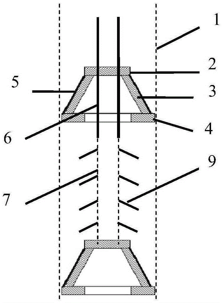
[0024] The main idea of ​​the embodiment of the present invention is that, according to the technical solution of the embodiment of the present invention, after the compressed air is injected through the gas injection pipe, the injected gas is released through the aeration system under the barrier effect of the first sealing device and the second s...


PUM


Abstract

The invention provides a multi-section type soil in-situ aerating device. The multi-section type soil in-situ aerating device comprises sealing devices, an air injecting pipe and an aerating pipe. The sealing devices include the first sealing device and the second sealing device, the first sealing device and the second sealing device are both in circular-truncated-cone shapes, and the first sealing device is connected to the air injecting pipe in a sleeving manner. The upper end of the air injecting pipe is connected with an aerating machine, and the lower end of the air injecting pipe penetrates the first sealing device to be connected with the aerating pipe. The upper end of the aerating pipe is connected with the lower end of the air injecting pipe, and the lower end of the aerating pipe is connected with the second sealing device. The aerating pipe comprises a vertical aerating pipe body, a plurality of pipe body holes are formed in the vertical aerating pipe body, each pipe body hole is connected with a branch aerating pipe, and a dip angle is formed between each branch aerating pipe and the vertical aerating pipe body. The first sealing device and the second sealing device are oppositely arranged in an aerating well, and closed space is formed by the first sealing device, the second sealing device and the well wall of the aerating well. The multi-section type soil in-situ aerating device in the embodiment has the beneficial effects that aerating is even, the energy consumption of an air injecting device is low, and operation is flexible; and the pollutant removal efficiency is improved.

Description

technical field [0001] The invention relates to the field of soil pollution restoration, in particular to a multi-stage soil in-situ aeration device. Background technique [0002] Soil aeration technology (AirSparging, AS) is an in-situ remediation technology for dealing with volatile organic pollutants in soil. Due to its advantages of low cost, high efficiency and in-situ construction, it is widely used in soil with small molecular weight. , Remediation of volatile organic pollutants. AS technology injects compressed air into the soil, and during the upward movement of the gas, volatile organic pollutants enter the gas phase from the soil, and then the air containing pollutants is treated through the gas phase extraction system, so as to achieve the purpose of removing pollutants. In addition, the injected air accelerates the removal of pollutants through aerobic biodegradation. [0003] However, through laboratory research and site engineering applications, it is found ...

Claims


Application Information

Patent Timeline
Patent Type & Authority Applications(China)
IPC IPC(8): B09C1/00
CPCB09C1/00B09C2101/00
Inventor 张洁琼李淑彦马志飞黄晓云罗章张志新
Owner 北京德瑞科森环保科技有限公司
Why Eureka
Try Eureka