A mechanism for the top plate of an injection mold to drive the screw to rotate and eject the mold

A technology that drives the screw and rotates out, which is applied in the field of the mechanism of the top plate of the injection mold driving the screw to rotate and eject the mold. It can solve the problems of high manufacturing and maintenance costs, strains, and low product quality, so as to improve the molding quality, manufacturing and maintenance costs. Low, simple structure and reliable effect

Active Publication Date: 2020-09-11
宁波正佳模塑有限公司
View PDF4 Cites 0 Cited by
  • Summary
  • Abstract
  • Description
  • Claims
  • Application Information

AI Technical Summary

Problems solved by technology

[0003] 1. The oil cylinder drives the gear to rotate the screw, and the screw rotates out of the product to release the product from the mold. The disadvantage is that the mold structure is complex, and the manufacturing and maintenance costs are high;
[0004] 2. The helical gear ejection method described in the patent No. 201320009916.4 (a spiral demoulding device for a helical gear injection mold). The cavity is driven to make a rotating motion, so that the product is ejected while rotating, and the helical tooth cavity is stationary. The disadvantage is that when the product is about to rotate and eject the helical tooth cavity, the remaining small part of the helical teeth on the product is relatively weak. , this part will be strained when it is ejected, and the quality of the formed product is low, which cannot meet the high requirements of the product

Method used


Image

  • A mechanism for the top plate of an injection mold to drive the screw to rotate and eject the mold
  • A mechanism for the top plate of an injection mold to drive the screw to rotate and eject the mold

Examples


Embodiment Construction

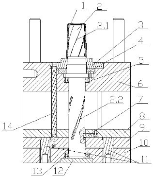
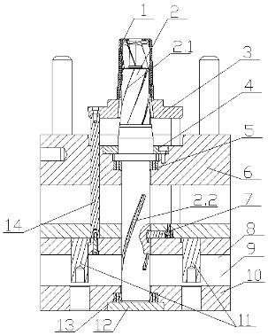
[0021] refer to figure 1 with figure 2 As shown, a mechanism for the top plate of an injection mold to drive the screw to rotate and eject the mold, including a product 1, a screw core 2, a push plate 3, a pressure plate 4, a first bearing 5, a movable template 6, a driving block 7, an upper top plate 8, a lower Top plate 9, bottom plate 10, pull reset 11, backing plate 12, second bearing 13 and first push rod 14, the upper part of the screw core 2 has a spiral undercut 2.1, which is attached to the inner side of the product 1, and the screw type There is a helical groove 2.2 on the lower part of the core 2, the helical pitch is the same as that of the helical undercut 2.1, and the helical groove 2.2 cooperates with the driving block 7.

[0022] The driving block 7 is fixed on the upper top board 8 and attached to the lower top board 9 .

[0023] The inside of the push plate 3 cooperates with the screw core 2, the push plate 3 has protruding features and fits with the pro...


PUM


Abstract

A mechanism of an injection mold for using a top plate to drive a screw to rotate and strip mold comprises a product, a screw rod core, a pushing plate, a pressing plate, a bearing, a moving mold plate, a driving block, an upper ejection plate, a lower ejection plate, a bottom plate, pulling and resetting pieces, a cushion plate, a bearing and a pushing rod, wherein a spiral inverted buckle is arranged at the upper portion of the screw rod core and attached to the inner side of the product; a spiral groove is formed in the lower portion of the screw rod core; the spiral pitch of the spiral groove is the same as the spiral pitch of the spiral buckle; the spiral groove is matched with the driving block; and the driving block on the ejection plate drives the screw rod core to rotate, however, the product doesn't rotate. According to the mechanism, the structure is simple and reliable, and manufacturing and maintaining cost is low. Besides, an existing problem, as described in an article with the patent number 201320009916.4, that strain is caused when mold stripping ends is solved, so that the molding quality of the product is improved. The mechanism belongs to the technical field of molding tools.

Description

technical field [0001] The invention belongs to the technical field of injection molds, in particular to a mechanism in which the top plate of the injection mold drives a screw to rotate and eject the mold. Background technique [0002] Injection molding products with a large helical angle (including helical gears) require helical ejection and demoulding. The existing technologies include: [0003] 1. The oil cylinder drives the gear to rotate the screw, and the screw rotates out of the product to release the product from the mold. The disadvantage is that the mold structure is complex, and the manufacturing and maintenance costs are high; [0004] 2. The helical gear ejection method described in the patent No. 201320009916.4 (a spiral demoulding device for a helical gear injection mold). The cavity is driven to make a rotating motion, so that the product is ejected while rotating, and the helical tooth cavity is stationary. The disadvantage is that when the product is abou...

Claims


Application Information

Patent Timeline
Patent Type & Authority Patents(China)
IPC IPC(8): B29C45/40
CPCB29C45/4005
Inventor 华小光
Owner 宁波正佳模塑有限公司
Why Eureka
Try Eureka