Cable channel drainage device for electrical equipment

A technology for power equipment and drainage device, applied in the field of electric power, can solve the problems of failure, blockage of drainage, and high cost, and achieve the effects of simple structure, thorough drainage, and prevention of blockage

Inactive Publication Date: 2016-01-20
蓝灿玉
View PDF0 Cites 3 Cited by
  • Summary
  • Abstract
  • Description
  • Claims
  • Application Information

AI Technical Summary

Problems solved by technology

[0002] In the power industry, substation wells and cable trenches are generally lower than the ground outside the substation. Whenever there is heavy rain, the substation wells and cable trenches tend to accumulate water. The use of underground natural drainage is likely to cause drainage failure due to blockage, causing cables to soak in In the water, it seriously threatens the safe operation of the substation
For this reason, some power supply companies install submersible pumps and drainage pipes in substation wells and cable trenches, and use artificial mechanical drainage, that is, manually observe the accumulation of water on a regular basis, and turn on the submersible pumps for drainage according to the water level. This operation is more complicated and time-consuming. Laborious, the labor intensity of the workers is relatively high
Therefore, it is very necessary to design a kind of automatic drainage device that can well solve the above problems, but the existing automatic drainage device has high cost, is easy to block, and does not drain thoroughly

Method used


Image

  • Cable channel drainage device for electrical equipment
  • Cable channel drainage device for electrical equipment
  • Cable channel drainage device for electrical equipment

Examples


Embodiment Construction

[0016] The following will clearly and completely describe the technical solutions in the embodiments of the present invention with reference to the accompanying drawings in the embodiments of the present invention. Obviously, the described embodiments are only some, not all, embodiments of the present invention. Based on the embodiments of the present invention, all other embodiments obtained by persons of ordinary skill in the art without making creative efforts belong to the protection scope of the present invention.

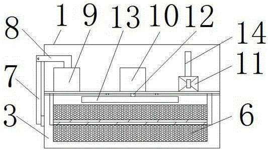
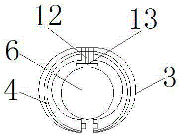
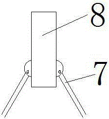
[0017] see Figure 1-5 , The present invention provides a technical solution: a cable trench drainage device for electric power equipment, including a housing 1, and a control panel on the side of the housing 1 is electrically connected to a water level sensor 2, a first cylinder 9, a second cylinder 10 and a water pump 11. The surface of the housing 1 is fixedly connected to the support frame, and a water level sensor 2 is provided at the bottom of one side o...


PUM


Abstract

The invention discloses a cable channel drainage device for electrical equipment. The cable channel drainage device for the electrical equipment comprises a shell, the surface of the shell is fixedly connected with a support frame, a water level sensor is arranged at the bottom of one side of a leg of the support frame, a partition plate is arranged in the shell, a movable cover is connected to the bottom of the partition plate through a connecting part, the movable cover is composed of two semicircular cover bodies which are each of a cavity structure, a hose is arranged in each cavity structure of the corresponding semicircular cover body, holes are formed in the bottom of the inner wall of the movable cover, absorbent cotton is arranged in the movable cover, and an elastic part is arranged on the middle part of the absorbent cotton. According to the cable channel drainage device for the electrical equipment, the water level sensor is arranged, when water accumulation occurs, a signal is transmitted to drainage equipment, and drainage treatment is conducted; due to the fact that the absorbent cotton is arranged, sundries such as sand are not sucked when the device sucks water, and blocking is prevented. The cable channel drainage device for the electrical equipment is simple in structure, and safe operation of a power line is guaranteed.

Description

technical field [0001] The invention relates to the technical field of electric power, in particular to a cable ditch drainage device for electric power equipment. Background technique [0002] In the power industry, substation wells and cable trenches are generally lower than the ground outside the substation. Whenever there is heavy rain, the substation wells and cable trenches tend to accumulate water. The use of underground natural drainage is likely to cause drainage failure due to blockage, causing cables to soak in In the water, it seriously threatens the safe operation of the substation. For this reason, some power supply companies install submersible pumps and drainage pipes in substation wells and cable trenches, and use artificial mechanical drainage, that is, manually observe the accumulation of water on a regular basis, and turn on the submersible pumps for drainage according to the water level. This operation is more complicated and time-consuming. Laborious, ...

Claims


Application Information

Patent Timeline
Patent Type & Authority Applications(China)
IPC IPC(8): E03F5/22
Inventor 蓝灿玉
Owner 蓝灿玉
Why Eureka
Try Eureka