Spray nozzle assembly

A technology of nozzles and components, applied to engine components, fuel injection devices, mechanical equipment, etc., to achieve good heat exchange, clear flow direction, and good cooling effect

Active Publication Date: 2016-01-20
TENNECO SUZHOU EMISSION SYST
View PDF8 Cites 6 Cited by
  • Summary
  • Abstract
  • Description
  • Claims
  • Application Information

AI Technical Summary

Problems solved by technology

[0004] However, since nozzles are often used in high-temperature environments, the research on cooling devices for nozzles has become a technical problem that technicians need to solve

Method used


Image

  • Spray nozzle assembly
  • Spray nozzle assembly
  • Spray nozzle assembly

Examples


Embodiment Construction

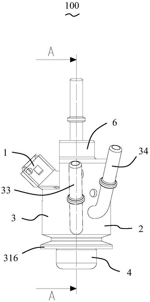
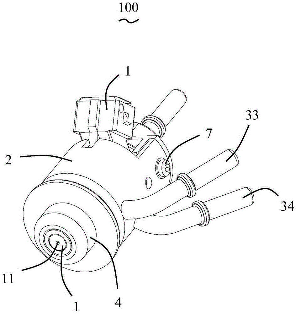
[0032] Please refer to Figure 1 to Figure 9 As shown, the present invention discloses a nozzle assembly 100 , which includes a nozzle 1 and a cooling jacket 2 surrounding the nozzle 1 . The nozzle 1 may be a urea nozzle or a fuel nozzle. The nozzle 1 includes a magnetic coil, a movable valve core, a valve seat matched with the valve core, and the like. The valve seat is provided with injection holes 11 . Since the structure of the nozzle 1 can be known by those skilled in the technical field, for example, reference can be made to the Chinese invention patent with the publication number CN102108891B, which will not be repeated here.

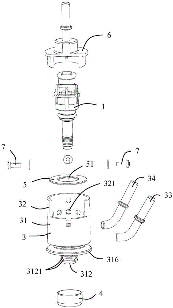
[0033] The cooling jacket 2 includes a cooling seat 3 , an end cover 4 located at the lower end of the cooling seat 3 , a sealing plate 5 fixed in the cooling seat 3 , and a cover 6 connected to the upper end of the cooling seat 3 .

[0034] Please refer to Figure 3 to Figure 7 As shown, the cooling base 3 includes a body portion 31 , a cyli...


PUM


Abstract

The invention discloses a spray nozzle assembly. The spray nozzle assembly is composed of a spray nozzle and a cooling sleeve which covers the periphery of the spray nozzle, wherein the cooling sleeve comprises a cooling base and an end cover positioned at the lower end of the cooling base; the cooling base is provided with a body part; the body part is provided with a mounting surface, a bump part which downwards extends out of the mounting base, a first channel positioned besides the bump part and a second channel positioned besides the bump part, wherein the first channel communicates with a liquid inlet tube; the end cover is sealed at the periphery of the bump part for forming a cooling cavity; by virtue of the cooling cavity, the first channel communicates with the second channel; and the cooling base further comprises a liquid outlet cavity which communicates with the second channel for further communicating with a liquid outlet tube. According to the spray nozzle assembly, a flow direction of a cooling liquid is relatively clear, good heat exchange can be realized, and cooling effect is better.

Description

technical field [0001] The invention relates to a nozzle assembly, which belongs to the technical field of engine exhaust aftertreatment. Background technique [0002] The exhaust of internal combustion engines, especially diesel engines, contains a large amount of nitrogen oxides and particulate matter, causing serious pollution to the atmosphere and endangering human health. It is urgent to reduce the emission of nitrogen oxides and particulate matter, and all countries have specific environmental regulations to regulate this. With the enhancement of human awareness of atmospheric protection, relevant laws and regulations promulgated at home and abroad are gradually becoming stricter. For this, it is necessary to use exhaust after-treatment technology to purify and treat the exhaust of internal combustion engines. [0003] In the field of engine exhaust post-treatment technology, nozzles mainly include urea nozzles and fuel nozzles, where the urea nozzles are used to spra...

Claims


Application Information

Patent Timeline
IPC IPC(8): F01N3/28F02M53/04F02M61/18
Inventor 樊高峰彭威波杨振球宋红卫
Owner TENNECO SUZHOU EMISSION SYST
Why Eureka
Try Eureka