Transmission shaft for automobile

A technology for transmission shafts and vehicles, applied in the directions of shafts, couplings, shafts and bearings, etc., can solve the difficulty of connecting the composite material pipe body and the metal joint, the extrusion damage at the opening, and the inability of the metal transmission shaft to interact with each other. Replacement and other issues, to achieve better weight loss effect, mature preparation method, light weight effect

Active Publication Date: 2016-01-20
绍兴宝旌复合材料技术研发有限公司
View PDF6 Cites 4 Cited by
  • Summary
  • Abstract
  • Description
  • Claims
  • Application Information

AI Technical Summary

Problems solved by technology

[0004] At present, composite material transmission shafts are rarely used in automobiles, especially on heavy-duty trucks with large loads. The main reason is that it is difficult to connect the composite material pipe body with the metal joint and the interchangeability is not good.
The traditional connection methods of pipe body and joint mainly include glue joint, spline joint and fastener joint, etc., but these methods have disadvantages: the joint strength is not strong, the construction is complicated, the joint quality is not easy to guarantee, and it is not easy to detect The spline connection can transmit small torque, but cannot transmit large axial force; the fastener connection needs to adopt the flange type joint, the bolt head protrudes from the surface of the pipe body, and the opening is prone to extrusion damage
Metal joints also vary and are not interchangeable with traditional metal drive shafts

Method used


Image

  • Transmission shaft for automobile
  • Transmission shaft for automobile
  • Transmission shaft for automobile

Examples


Embodiment 1

[0030] Design and preparation technology of the present invention are described in further detail below by embodiment

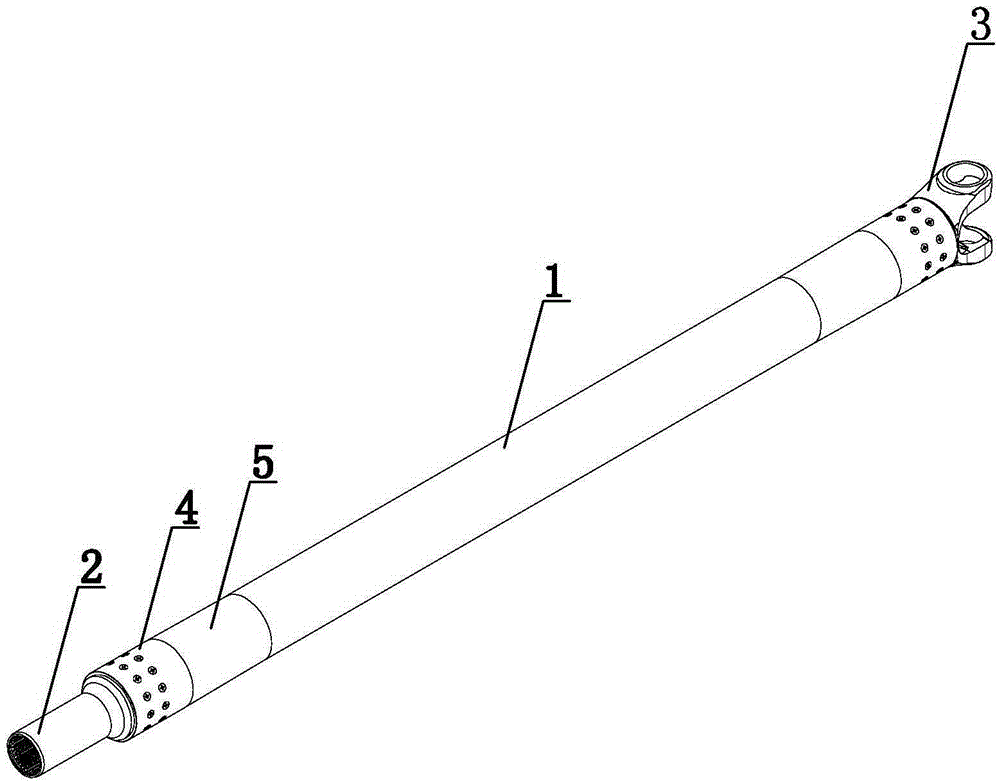
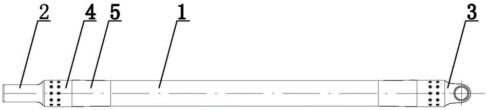
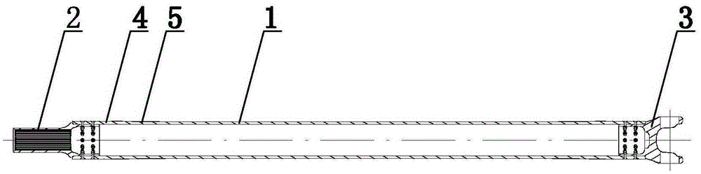
[0031] In this embodiment, a transmission shaft for a vehicle is combined with figure 1 , figure 2 and image 3 , consisting of a pipe body 1, a splined sleeve 2 and a universal joint fork 3, the splined sleeve 2 and the universal joint fork 3 are respectively arranged at both ends of the pipe body 1, and the pipe body 1 and the splined sleeve 2, A slope transition area 4 is set between the pipe body 1 and the universal joint fork 3, and the slope transition area 4 is integrated with the pipe body 1; Figure 4 , The pipe body 1 and the spline sleeve 2, the pipe body 1 and the universal joint fork 3 are fixed by the cooperation of the countersunk bolt 6 and the self-locking nut 7 .

[0032] which, combined with Figure 5 , the pipe body 1 is a layered structure formed by laying layers 13 at different angles. The laying layers 13 are laid symmetrically alo...

Embodiment 2

[0047] The setting and working principle of this embodiment are the same as that of Embodiment 1, the difference is that:

[0048] combine figure 1 , figure 2 and image 3 , consisting of a pipe body 1, a splined sleeve 2 and a universal joint fork 3, the splined sleeve 2 and the universal joint fork 3 are respectively arranged at both ends of the pipe body 1, and the pipe body 1 and the splined sleeve 2, A slope transition area 4 is set between the pipe body 1 and the universal joint fork 3, and the pipe body 1 is provided with a thick placement area 5 near the slope transition area 4, which is used to strengthen the strength of the connection part, and the slope transition area 4 , the thick placement area 5 and the pipe body 1 are of an integrated structure; combined Figure 4 , The pipe body 1 and the spline sleeve 2, the pipe body 1 and the universal joint fork 3 are fixed by the cooperation of the countersunk bolt 6 and the self-locking nut 7 .


PUM


Abstract

The invention relates to a transmission shaft for an automobile and belongs to the technical field of traffic facilities. The transmission shaft is composed of a pipe body, a spline sleeve and a universal joint fork. The spline sleeve and the universal joint fork are arranged at the two ends of the pipe body respectively. A slope transition area is arranged between the pipe body and the spline sleeve, and a slope transition area is arranged between the pipe body and the universal joint fork. The transmission shaft is applied to traffic facilities such as automobiles and has the beneficial effects of being convenient to mount and demount, reliable in connection, good in interchangeability and the like.

Description

technical field [0001] The invention relates to a transmission shaft for vehicles and belongs to the technical field of traffic facilities. Background technique [0002] The car drive shaft is the part that connects the gearbox and the drive axle, and finally transmits the power generated by the engine to the wheels to drive the car. Reducing the weight of the transmission system can reduce the energy consumption during operation and improve the efficiency of the engine. [0003] The composite transmission shaft has low density, high rigidity, small twist rate, high critical speed, and the shaft can be made longer. Two sections of metal transmission shaft can be combined into one section, and the support structure between the two sections is omitted, reducing weight. Obviously, compared with the traditional metal transmission shaft, the composite material transmission shaft with a length of 2 meters can reduce the weight by more than 50%. It also has the characteristics of ...

Claims


Application Information

Patent Timeline
Patent Type & Authority Applications(China)
IPC IPC(8): F16C3/02F16D3/16B60K17/22
Inventor 戈家荣陈立峰胡纪根张卉梓沈伟
Owner 绍兴宝旌复合材料技术研发有限公司
Why Eureka
Try Eureka