Wafer-level capacitive acceleration meter automatic testing system

An automatic test system and accelerometer technology, applied in the direction of speed/acceleration/shock measurement, test/calibration of speed/acceleration/shock measurement equipment, measurement device, etc. Test methods, etc.

Active Publication Date: 2016-01-20
EAST CHINA INST OF OPTOELECTRONICS INTEGRATEDDEVICE
View PDF9 Cites 5 Cited by
  • Summary
  • Abstract
  • Description
  • Claims
  • Application Information

AI Technical Summary

Problems solved by technology

[0003] However, in the wafer stage of the capacitive accelerometer, because the chip is placed on the probe station and is in a flat state, external acceleration signals such as mechanical shock and vibration cannot be applied to the capacitive accelerometer chip. Therefore, for the capacitive accelerometer at the wafer stage Accelerometer, unable to follow its finished product test method

Method used


Image

  • Wafer-level capacitive acceleration meter automatic testing system
  • Wafer-level capacitive acceleration meter automatic testing system

Examples


Embodiment 1

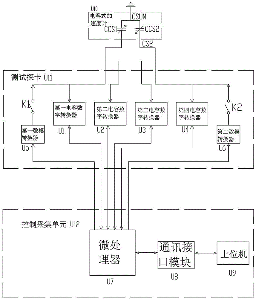
[0012] Such as figure 1 As shown, the present invention provides a wafer-level capacitive accelerometer automatic test system, including a microprocessor U7 and an upper computer U9 connected to the microprocessor U7 through a communication interface module U8, the microprocessor U7, the communication interface module U8 and the upper computer The machine U9 constitutes the control acquisition unit U12; the system also includes four capacitance-to-digital converters, that is, the first capacitance-to-digital converter U1, the second capacitance-to-digital converter U2, the third capacitance-to-digital converter U3, and the fourth capacitance-to-digital converter converter U4, the system also includes a first digital-to-analog converter U5, a second digital-to-analog converter U6, a first relay K1 and a second relay K2; the first relay K1 and the second relay K2 are respectively controlled by the microprocessor The switch U7 controls the on-off, that is, the output interface of...

Embodiment 2

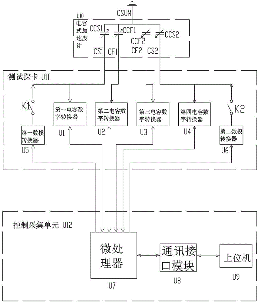
[0017] Such as figure 2 As shown, the structure of the wafer-level capacitive accelerometer automatic test system in this embodiment is basically the same as that in Embodiment 1, and also includes a microprocessor U7, a first capacitance-to-digital converter U1 to a fourth capacitance-to-digital converter U4, a second capacitance-to-digital converter A digital-to-analog converter U5, a second digital-to-analog converter U6, a first relay K1 and a second relay K2; the first relay K1 and the second relay K2 are respectively controlled on and off by the microprocessor U7, that is, the microprocessor The U7 output interface is respectively connected to the coils of the first relay K1 and the second relay K2 (not shown in the figure); the output interface of the microprocessor U7 is respectively connected to the input of the first digital-to-analog converter U5 and the second digital-to-analog converter U6 Interface, the output interface of the first digital-to-analog converter U...


PUM


Abstract

The invention discloses a wafer-level capacitive acceleration meter automatic testing system comprising a microprocessor, a host computer connected with the microprocessor, four capacitive digital converters, a first digital-to-analog converter, a second digital-to-analog converter, a first relay, and a second relay. The microprocessor controls the digital-to-analog converters and the relays, applies DC voltage to the two fixed electrodes of a capacitive acceleration meter at different time in order to generate electrostatic force and simulate external acceleration. The four capacitive digital converters are controlled by the microprocessor and transmit the capacitance values, acquired at different time, of the capacitive acceleration meter to the microprocessor. A capacitance change value is calculated by the microprocessor. The wafer-level capacitive acceleration meter automatic testing system achieves a purpose of testing a parameter and determines the quality of the capacitive acceleration meter.

Description

technical field [0001] The invention relates to the field of microelectronic testing, in particular to a wafer-level capacitive accelerometer automatic testing system. Background technique [0002] As is known, the capacitive accelerometer is a differential capacitance structure, which has a movable plate and a plurality of fixed electrodes inside, the movable plate is connected to the mass block, and a plurality of fixed electrodes are opposite to it, between the movable plate and the fixed electrode A differential capacitance pair is formed between the electrodes. When an external acceleration is applied to the capacitive accelerometer, its internal mass is displaced, which causes the differential capacitance pair inside the accelerometer to change, thereby causing the differential capacitance value of the differential capacitance to change. Utilize this feature, apply mechanical shock or vibration to the finished circuit of the packaged accelerometer, provide an accelerat...

Claims


Application Information

Patent Timeline
Patent Type & Authority Applications(China)
IPC IPC(8): G01P21/00
Inventor 田波方岚焦贵忠谢斌郑宇
Owner EAST CHINA INST OF OPTOELECTRONICS INTEGRATEDDEVICE
Why Eureka
Try Eureka