
Light beam combining system and projection apparatus therefor

A technology of projection device and optical system, applied in projection devices, optics, optical components, etc., can solve the problems of large optical path, unfavorable projector volume and weight, etc., to achieve the effect of enhancing light intensity, good visual enjoyment, and improving performance

Active Publication Date: 2016-01-20
IVIEW DISPLAY SHENZHEN CO LTD
View PDF6 Cites 3 Cited by
  • Summary
  • Abstract
  • Description
  • Claims
  • Application Information

AI Technical Summary

Problems solved by technology

[0004] Existing conventional projectors usually combine a group of three primary color light sources into parallel light beams, and then change the direction of the light beams through devices such as reflectors to make the light beams incident on the display chip; at present, in order to enhance the light intensity, the projection In order to improve the performance of the machine, two sets of tri-primary light sources are used as the light source device. If the above-mentioned reflectors and other devices are used to change the direction of the light beams of the two sets of tri-primary light sources so that the light beams are incident on the display chip, the optical path will be relatively large, which is not conducive to reducing the Projector size and weight

Method used


Image

  • Light beam combining system and projection apparatus therefor
  • Light beam combining system and projection apparatus therefor
  • Light beam combining system and projection apparatus therefor

Examples


Embodiment Construction

[0025] The specific embodiments of the present invention will be described in detail below in conjunction with the accompanying drawings, but it should be understood that the protection scope of the present invention is not limited by the specific embodiments.

[0026] Unless expressly stated otherwise, throughout the specification and claims, the term "comprise" or variations thereof such as "includes" or "includes" and the like will be understood to include the stated elements or constituents, and not Other elements or other components are not excluded.

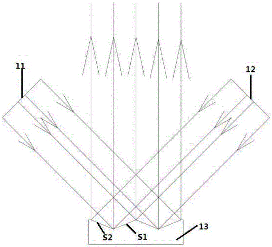
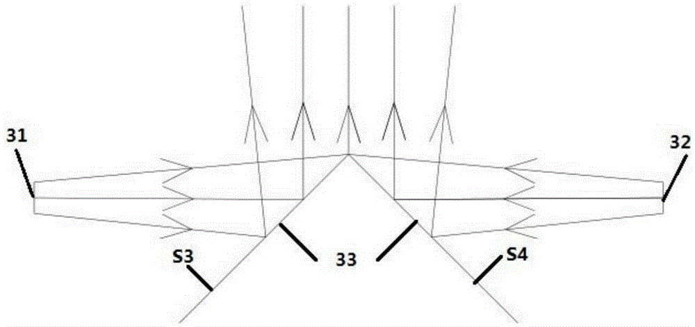
[0027] refer to figure 1 with figure 2 ; figure 1 It is a structural schematic diagram of the first embodiment of the beam combination system of the present invention; figure 2 It is a schematic cross-sectional view of the light combining device in the first embodiment of the light beam combining system of the present invention. In this embodiment, the light combining device is a zigzag lens. Such as figure 1 with ...


PUM


Abstract

The invention provides a light beam combining system and an application of the light beam combining system in a projection apparatus. The light beam combining system comprises a first light beam and a second light beam from different incidence directions; and a light combining apparatus for enabling the first light beam and the second light beam to be reflected, and enabling the reflected light beam to be propagated in the same direction; the light combining apparatus a first reflecting surface for reflecting the first light beam and a second reflecting surface for reflecting the second light beam; the light beam combining system adopts the light combining apparatus to combine the two light beams from the different incidence directions to enable the two light beams to be focused into the light beam of the same direction, so that the illumination intensity of the light beam is greatly increased to further improve the performance of the projection apparatus adopting the light combining system on the condition of ensuring the size and the weight conditions, and better view enjoyment is brought for users.

Description

technical field [0001] The invention relates to the technical field of digital projection display, and more specifically, to a light beam combining system and a projection device thereof. Background technique [0002] With the development of science and technology, especially the advancement of semiconductor technology, portable electronic devices are constantly being designed and manufactured. The improvement of the functions of portable electronic devices has made the user's requirements for the display devices of the human-machine interface more and more developed towards the direction of miniature, large screen and high resolution. Driven by the strong demand of the majority of users, projector technology has developed rapidly in recent years. DLP, LCOS and other products have launched portable projectors with high performance, small size and light weight. [0003] The function of the illumination light path of the projection module in the projector is to convert as muc...

Claims


Application Information

Patent Timeline
Patent Type & Authority Applications(China)
IPC IPC(8): G03B21/20G02B27/14
CPCG02B27/14G03B21/20G03B21/2033G03B21/2066
Inventor 高志强赵远杨伟樑林清云
Owner IVIEW DISPLAY SHENZHEN CO LTD
Learn More