
Method and apparatus for identifying inertial parameters of object to be identified

A technology for identifying targets and inertial parameters, applied in the field of inertial parameter identification devices, can solve problems such as poor generality, low measurement accuracy of angular acceleration signals and torque information, and complex inertial parameter identification process, so as to save fuel and avoid adverse effects. Effect

Active Publication Date: 2016-01-20
INST OF MECHANICS - CHINESE ACAD OF SCI
View PDF1 Cites 23 Cited by
  • Summary
  • Abstract
  • Description
  • Claims
  • Application Information

AI Technical Summary

Problems solved by technology

[0009] The above-mentioned method one needs to use the booster to push the unknown target, so it will consume the fuel of the spacecraft; in addition, due to the low measurement accuracy of the current angular acceleration signal and torque information, the accuracy of the inertial parameters obtained by using the method one lower;
[0010] The above-mentioned method 2 requires a sufficient number of equations to solve the inertial parameters. Therefore, it is necessary to drive the arm joints to move multiple times, and the identification process of the inertial parameters is more complicated; In the case of low linear momentum measurement accuracy, the inertia parameters obtained by method 2 have low accuracy;
[0011] The above-mentioned method three, because its inertial parameter identification is based on the sample library, limits the range of identifiable unknown targets, that is, the method has poor versatility; In the case of a large number of samples, the difficulty of designing and training the multi-layer feedforward neural network is relatively high.

Method used


Image

  • Method and apparatus for identifying inertial parameters of object to be identified
  • Method and apparatus for identifying inertial parameters of object to be identified
  • Method and apparatus for identifying inertial parameters of object to be identified

Examples


Embodiment 1

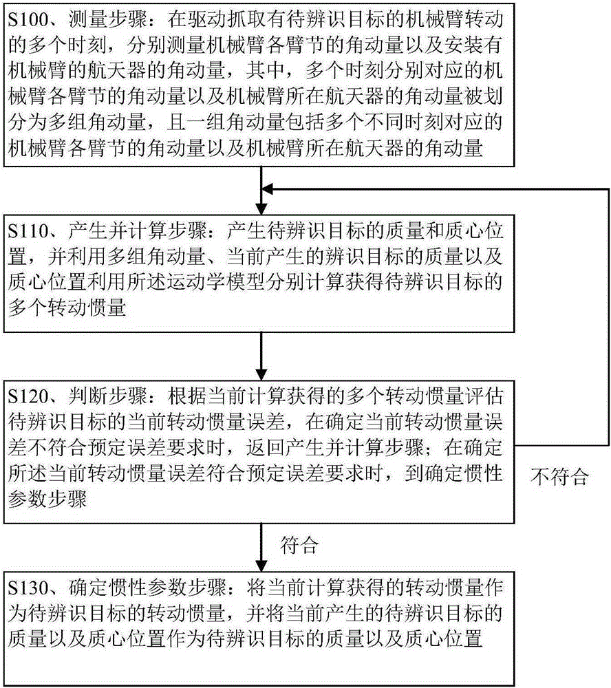
[0031] Embodiment 1. A method for identifying inertial parameters of a target to be identified.

[0032] The method of this embodiment can enable the spacecraft equipped with a robotic arm to effectively identify (for example, on-orbit identification) the inertial parameters of the target to be identified (ie, the unknown target). The inertial parameters of the object to be identified in this embodiment refer to the mass, the position of the center of mass and the moment of inertia of the object to be identified. In this embodiment, the position of the center of mass of the object to be identified is usually the three-dimensional coordinates of the center of mass, that is, the mass and the position of the center of mass of the object to be identified are four scalar quantities.

[0033] A star-arm coupling system is formed between the spacecraft and the mechanical arm in this embodiment. For example, the mechanical arm includes n-1 arm segments (such as an arm segment comprisi...

Embodiment 2

[0116] Embodiment 2, the inertial parameter identification method of the target to be identified.

[0117] First, at multiple moments when the manipulator grabs the target to be identified, the angular momentum of each arm segment of the manipulator and the angular momentum of the spacecraft where the manipulator is located are measured respectively.

[0118] Secondly, the mass and the position of the center of mass of the target to be identified are generated. When the quality and centroid position of the target to be identified is not generated for the first time, the basic genetic algorithm with real-value coding can be used. The implementation process of the basic genetic algorithm can include: assigning fitness based on linear sorting, and selecting with the roulette method, The optimization interval is limited to the conservatively estimated mass and the boundary range of the centroid position, etc. This embodiment does not limit the specific implementation process of t...

Embodiment 3

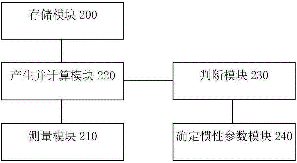
[0128] Embodiment 3: An inertial parameter identification device for a target to be identified. The structure of the device is as figure 2 shown.

[0129] figure 2 Among them, the inertial parameter identification device of the target to be identified in this embodiment mainly includes: a storage module 200 , a measurement module 210 , a generation and calculation module 220 , a judgment module 230 and a determination module 250 of inertial parameters.

[0130] The storage module 200 is mainly adapted to store a kinematics model for solving the moment of inertia of the target to be identified based on the principle of conservation of angular momentum of the multi-rigid body system.

[0131] Specifically, the kinematics model stored in the storage module 200 can be expressed by the following formula:

[0132] A I n ...


PUM


Abstract

The present invention discloses a method and apparatus for identifying inertial parameters of an object to be identified. The method includes the steps as follows: measuring the angular momentum of various arm sections of a mechanical arm and the angular momentum of a spacecraft at a plurality of points in time that the mechanical arm is driven to rotate for grabbing the object to be identified; generating the mass and mass center position of the object to be identified, and calculating out a plurality of inertia moments of the object to be identified by utilizing the several groups of angular momentum and the current generated mass and mass center position of the object to be identified according to a preset kinetic model; evaluating the current inertia moment error of the object to be identified according to the current acquired inertia moments, returning to the generating and calculating processes when the error does not accord with a preset error requirement, and otherwise, employing the current calculated out inertia moment, the current generated mass and mass centre of the object to be identified as the inertia moment, the mass and mass centre position of the object to be identified. According to the invention, the valuable fuel of the spacecraft is saved, the inertial parameter identification precision of the object to be identified is improved, and the ideal general purpose is provided.

Description

technical field [0001] The invention relates to space robot technology, in particular to an inertial parameter identification method for an object to be identified and an inertial parameter identification device for an object to be identified. Background technique [0002] Spacecraft such as satellites are usually equipped with a multi-arm robotic arm. During the in-orbit operation of the spacecraft, it often occurs that the robotic arm is used to grab unknown targets (also called non-cooperative targets or targets to be identified). Requirements; The unknown target here refers to the target whose inertial parameters such as mass, center of mass position and moment of inertia are unknown (such as partially unknown or completely unknown). [0003] In the process of controlling the manipulator to grasp the unknown target, the inertial parameters of the unknown target should be accurately and timely identified, otherwise, the grasping of the unknown target will cause unpredicta...

Claims


Application Information

Patent Timeline
IPC IPC(8): G05B17/02
Inventor 马欢张珩李文皓肖歆昕
Owner INST OF MECHANICS - CHINESE ACAD OF SCI
Learn More