
Power switch cabinet protection system

A protection system and switchgear technology, applied in the direction of emergency protection circuit devices, electrical components, etc., can solve the problems of increased switching workload, heavy workload, and difficult maintenance, so as to improve competitiveness, improve reliability, and simplify construction Effect

Inactive Publication Date: 2016-01-20
陈薇
View PDF8 Cites 7 Cited by
  • Summary
  • Abstract
  • Description
  • Claims
  • Application Information

AI Technical Summary

Problems solved by technology

However, a large number of these devices are applied to a power switch cabinet at the same time, causing many problems: first, various devices need to collect the same signal, for example, microcomputer relay protection devices, intelligent control instruments and intelligent measurement and control instruments, they all need Collect three-phase voltage and current signals and state signals, and provide different measurement, monitoring and protection functions for the switchgear through their respective algorithms, which doubles the workload of switch design, production, testing and maintenance; secondly, due to These smart devices provide communication interfaces for centralized monitoring. For the communication of these devices, one or more communication networks are usually laid for each type of device, which makes the on-site construction workload huge, reduces the reliability of the communication system, and makes maintenance difficult. It has been greatly improved; again, smart devices are usually installed on the instrument door of the switch cabinet, and the external dimensions of the switch are determined, and the size of the instrument door is also quite limited; more and more smart devices appear, making them on the switch cabinet The installation process has evolved into a jigsaw puzzle; the integration of smart devices in switchgear has become a mainstream demand

Method used


Image

  • Power switch cabinet protection system
  • Power switch cabinet protection system
  • Power switch cabinet protection system

Examples


Embodiment Construction

[0019] The following will clearly and completely describe the technical solutions in the embodiments of the present invention with reference to the accompanying drawings in the embodiments of the present invention. Obviously, the described embodiments are only some, not all, embodiments of the present invention. Based on the embodiments of the present invention, all other embodiments obtained by persons of ordinary skill in the art without making creative efforts belong to the protection scope of the present invention.

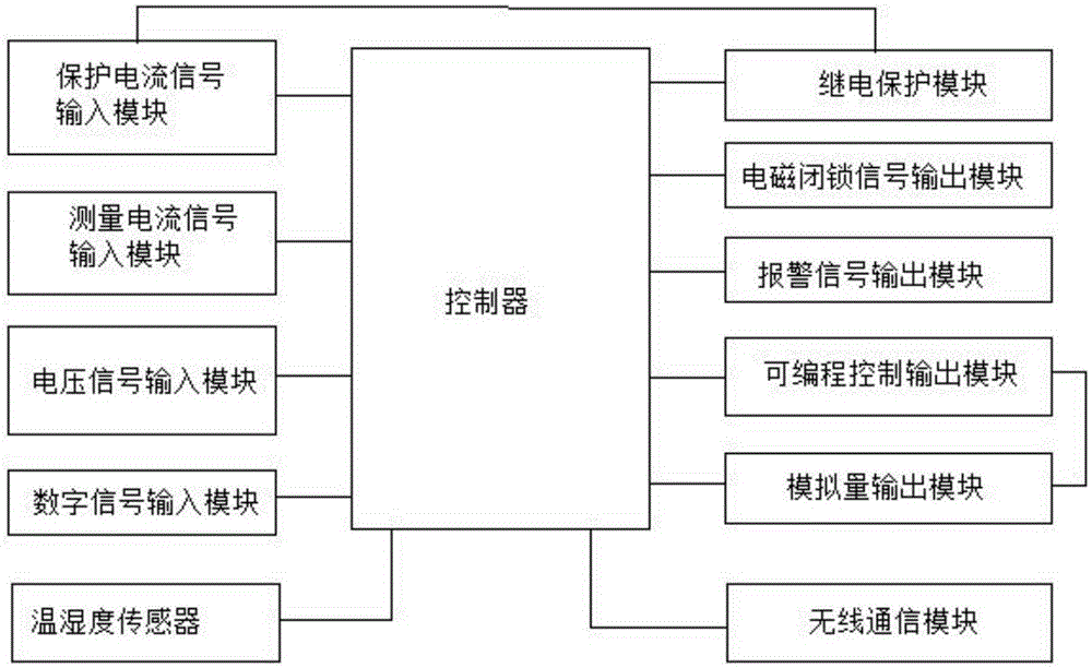
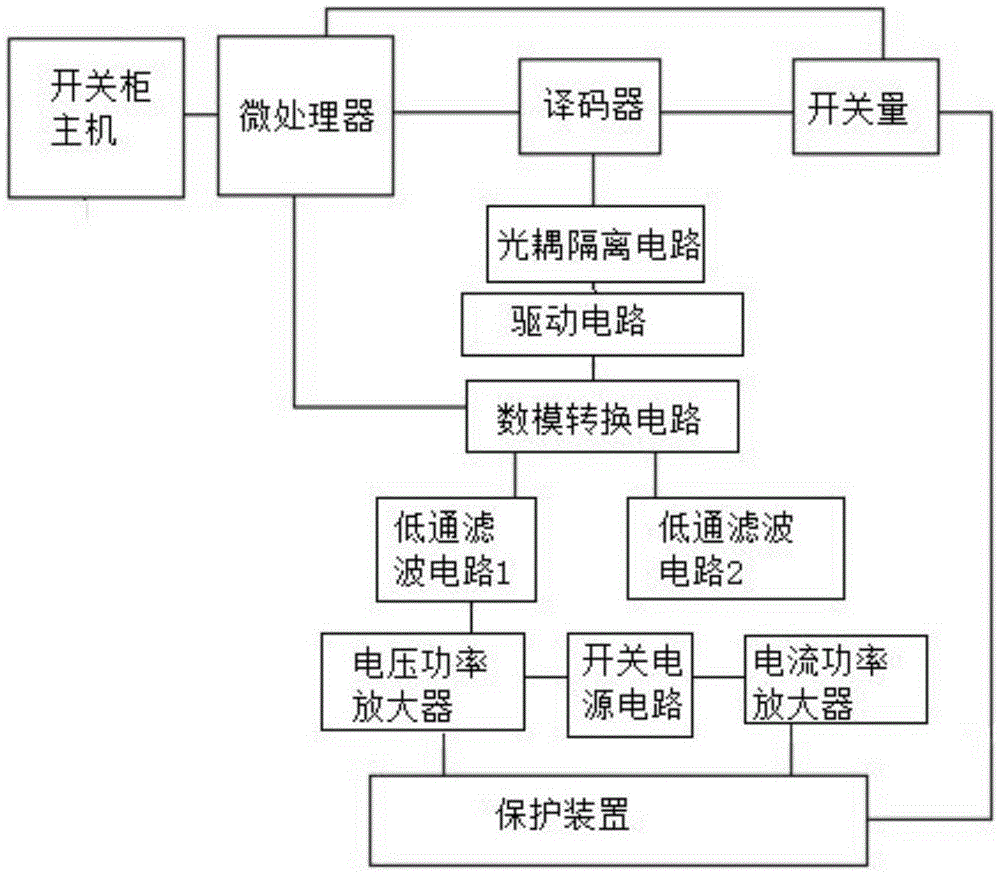
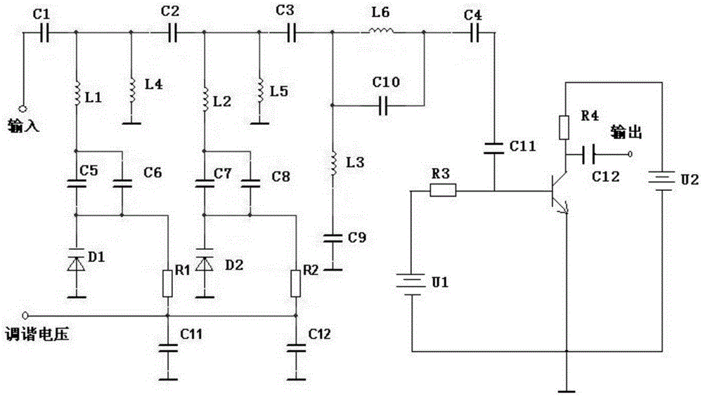
[0020] see Figure 1~3 , in an embodiment of the present invention, a power switch cabinet protection system includes a controller, a protection current signal input module, a voltage signal input module, a digital signal input module, a wireless communication module, an analog output module, and a programmable control output module, The controller is respectively connected to a protection current signal input module, a measurement current signal input module,...


PUM


Abstract

The invention discloses a power switch cabinet protection system. The system comprises a controller, a protection current signal input module, a voltage signal input module, a digital signal input module, a wireless communication module, an analog quantity output module, and a programmable control output module. The power switch cabinet protection system is multifunctional, the production of a switch cabinet intelligent protection measurement and control apparatus and the construction of an on-site communication network are simplified, the workload for links of production, test, installation, debugging, and maintenance of the switch cabinets is greatly reduced, and the problem of heavy workload of test, installation, debugging, and maintenance in the conventional production process of the switch cabinets due to various kinds and quantities of intelligent measurement and control equipment is overcome; and since the current power equipment competition is especially more and more fierce, the optimization of the cost for design, manufacture, test, installation, debugging, and maintenance of the switch cabinets and the improvement of the system reliability are the shortcut for improving the competitiveness of equipment manufacturing enterprises.

Description

technical field [0001] The invention relates to a protection system, in particular to a protection system for a power switch cabinet. Background technique [0002] In today's era of rapid development of power system automation level, there are more and more automation devices and systems applied to power systems, and their functions are becoming more and more complex; for example: microcomputer relay protection devices, intelligent control instruments, intelligent measurement and control instruments, temperature and humidity automatic Controller, contact temperature measurement system, etc.; this provides a strong support for the safety and reliability of the power supply system and its equipment. However, a large number of these devices are applied to a power switch cabinet at the same time, causing many problems: first, various devices need to collect the same signal, for example, microcomputer relay protection devices, intelligent control instruments and intelligent measu...

Claims


Application Information

Patent Timeline
IPC IPC(8): H02H7/22
Inventor 陈薇
Owner 陈薇
Learn More