
Reactive Power and Voltage Calibration Method Based on Limit Operation Mode

A technology of operation mode and limit, applied in the direction of reactive power compensation, AC network voltage adjustment, etc., can solve the problems of refining and summarizing reactive power and voltage checking methods.

Active Publication Date: 2018-02-02
ELECTRIC POWER RES INST OF EAST INNER MONGOLIA ELECTRIC POWER +1
View PDF4 Cites 0 Cited by
  • Summary
  • Abstract
  • Description
  • Claims
  • Application Information

AI Technical Summary

Problems solved by technology

Although various local power grids may have carried out reactive power and voltage calibration work, they have not refined and summarized the reactive power and voltage calibration methods. This work is purely based on the experience of technicians, and there is currently no method to follow

Method used


Image

  • Reactive Power and Voltage Calibration Method Based on Limit Operation Mode
  • Reactive Power and Voltage Calibration Method Based on Limit Operation Mode
  • Reactive Power and Voltage Calibration Method Based on Limit Operation Mode

Examples


Embodiment 1

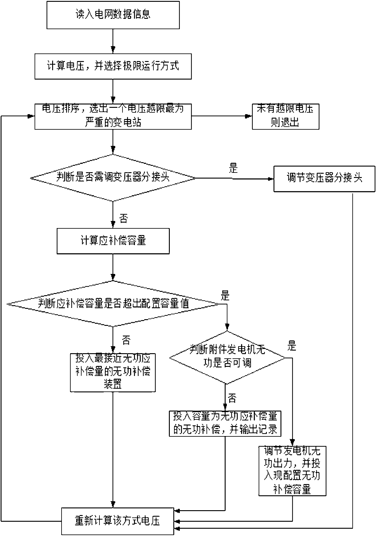
[0052] figure 1 It is a flow chart of the reactive voltage calibration method based on the limit operation mode. Such as figure 1 As shown, the reactive voltage calibration method based on the limit operation mode proposed by the present invention includes:

[0053] Step 1: Read in the data information of the researched power grid.

[0054] The data information includes the maximum and minimum loads of plants and stations in summer, the maximum and minimum output of each unit in summer, and the maximum and minimum loads of plants and stations in winter, and the maximum and minimum output of units in winter within the scope of the power grid under study; Configuration of power devices: configuration of reactive power compensation devices Q Cmax , Q Lmax , setting of transformer gear taps; actual reactive power operation: the current actual switching status of reactive power compensation device Q Cr , Q Lr , information on the gear position of the current voltage transform...

Embodiment 2

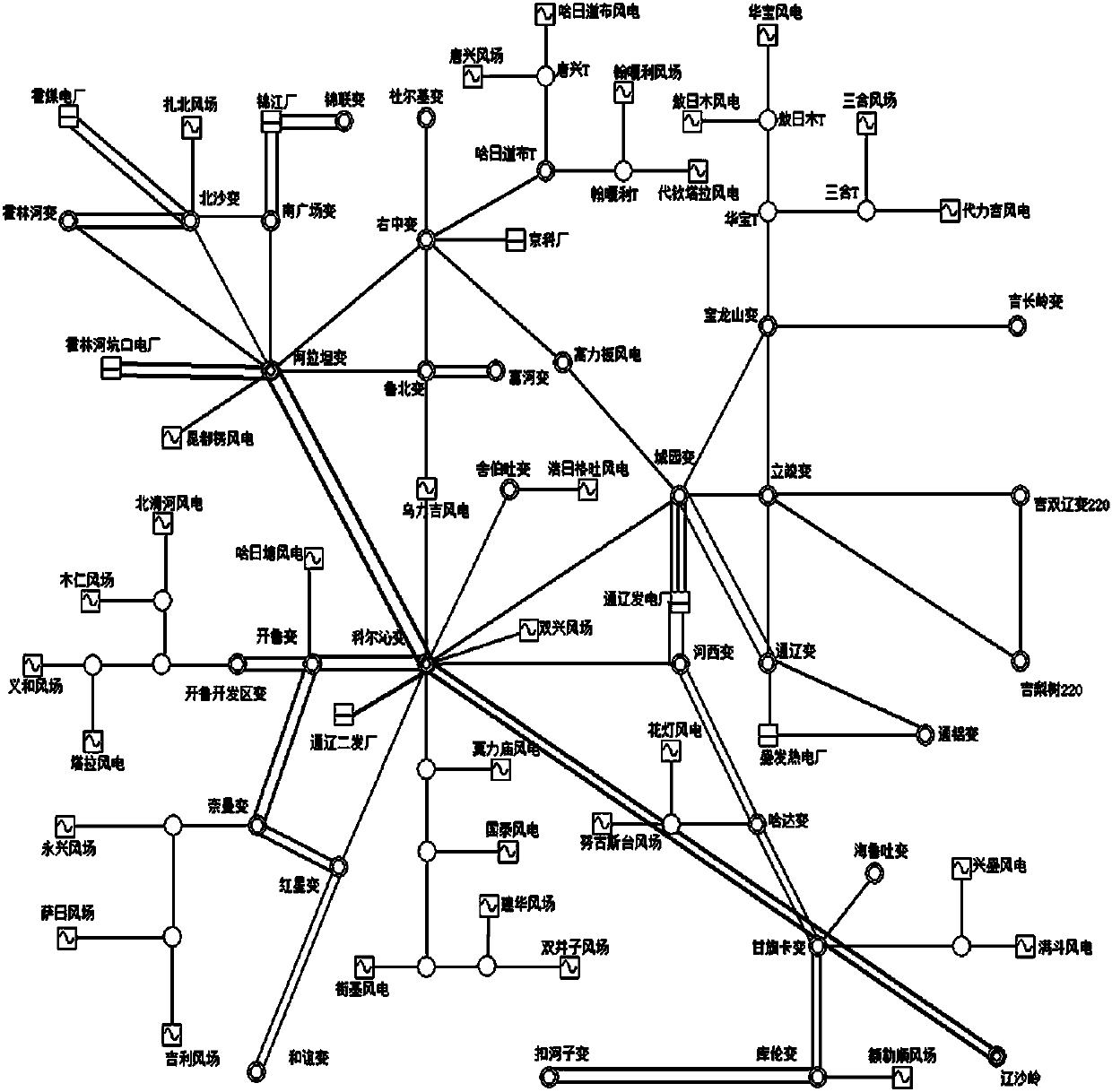
[0090] The content of the present invention will be further described below by taking the power grid in Tongliao, Inner Mongolia in 2015 as an embodiment of the present invention.

[0091] Wiring diagram of power grid in Tongliao area, Inner Mongolia figure 2 shown. Among them, the voltage control requirements of Tongliao power grid: 500kV bus voltage is controlled between 520-540kV, 220kV substation bus voltage is controlled between 220-237; all 220kV bus voltages of wind farm step-up substations need to be controlled between 225-235kV.

[0092] Through the calculation of the four operating modes, the selected Tongliao power grid voltage limit operating modes are:

[0093] The maximum load in summer and the minimum output of the unit in summer are used as the low-voltage limit operation mode;

[0094] The minimum load in summer and the maximum output of the unit in summer are used as the high-voltage limit operation mode.

[0095] Sorting the voltage calculation results o...

Embodiment 3

[0102] In step 2 in Embodiment 1 of the present invention, the calculation voltage can also be calculated by various calculation methods such as the Newton-Raphson method to perform power flow calculations for the four operating modes to obtain the bus voltages, which are not limited to one power flow calculation method;

[0103] In the Newton-Raphson polar coordinate method, the correction equation of the power flow equation is formula (1), and the voltage calculation formula (2) can be deduced from formula (1), and the specific calculation formulas of each item in formula (2) are (3)-( 10);

[0104]

[0105]

[0106]

[0107]

[0108]

[0109]

[0110]

[0111]

[0112]

[0113]

[0114] Among them, in formula (2), ΔP is the correction value of injected active power; ΔQ is the correction value of injected reactive power; H, N, J, L are the elements of Jacobian matrix; Δδ is the correction value of voltage phase angle, Δδ i Characterizes the volt...


PUM


Abstract

The invention belongs to the technical field of the reactive voltage control over a power grid and more particularly relates to a reactive voltage verification method based on a limit operation mode. According to the method, firstly, through reading the data information of the power grid, four operation modes are formed, and then a limit operation mode is selected based on the calculation result of a comparison voltage. Secondly, a substation of the worst voltage exceeding condition is selected, and whether the two-side / three-side voltage of a substation transformer exceeds a voltage upper limit Umax or a voltage lower limit Umin or not is examined. Thirdly, a compensation factor epsilon is set and the amount of reactive power compensation QC / QL of the substation is calculated. Fourthly, whether the sum of the amount of reactive power compensation QC / QL and the actual input QCr / QLr of the reactive power compensation exceeds a pre-configured capacity QCmax / QLmax of the reactive power compensation or not is judged. Fifthly, the voltage is re-calculated based on the above adjustment. The above process is circularly conducted till no voltage exceeds the upper / lower limit. According to the invention, based on the calculation of limit operation modes, whether the configuration status of reactive power compensation equipment meets the requirements of the relevant provisions and the requirement of voltage adjustment or not can be effectively verified, so that the decision-making process of the power grid operation is guided. Meanwhile, the blank in reactive voltage checking method is filled, and the above method is more applicable to the actual operation status of the power grid. Therefore, the method is suitable for online application.

Description

technical field [0001] The invention belongs to the technical field of power grid reactive voltage control, and in particular relates to a reactive voltage checking method based on a limit operation mode. Background technique [0002] In the current power system, with the continuous increase of load and the continuous development of various new projects such as UHV, reactive power and voltage control is facing various new challenges. In order to ensure the quality of grid voltage operation, it is necessary to check the reactive power and voltage conditions of the grid, master the configuration of reactive power compensation equipment in the grid, check whether relevant regulations and voltage adjustment requirements are met, and optimize reactive power, energy saving and loss reduction, and AVC systems. Build the foundation. Reactive power and voltage calibration is an indispensable task in the construction of smart grid, which is of great significance to the safety, stabil...

Claims


Application Information

Patent Timeline
Patent Type & Authority Patents(China)
IPC IPC(8): H02J3/16
CPCY02E40/30
Inventor 李袖刘景远吴晓丹陈肖璐李卓男刘翠霞欧阳强苏鹏韩晋思宋洋
Owner ELECTRIC POWER RES INST OF EAST INNER MONGOLIA ELECTRIC POWER
Learn More