Rotary ultrasonic vibration excitation device and time-space phase tuning method
An excitation device and rotating ultrasonic technology are applied in the direction of electrical components, piezoelectric effect/electrostrictive or magnetostrictive motors, generators/motors, etc., which can solve the drift of operating points, affect stability and work efficiency, Affect the excitation efficiency and other issues to achieve the effect of improving flexibility, making up for the drift of the working point, and improving the excitation efficiency
- Summary
- Abstract
- Description
- Claims
- Application Information
AI Technical Summary
Problems solved by technology
Method used
Image
Examples
Embodiment 1
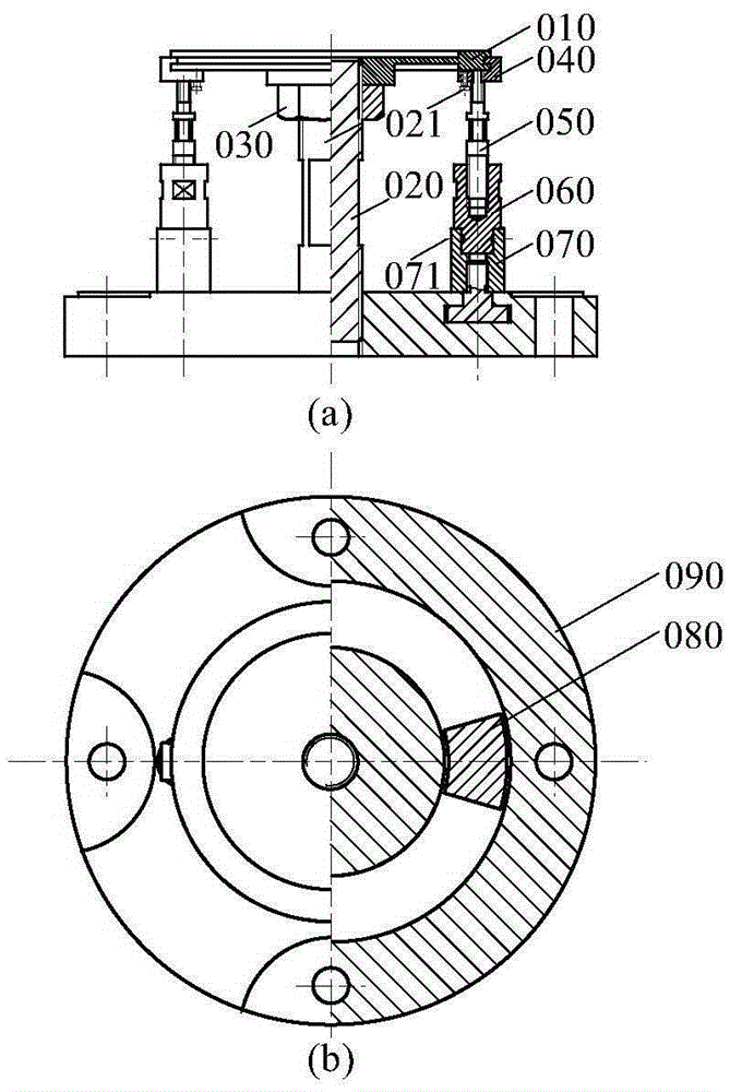
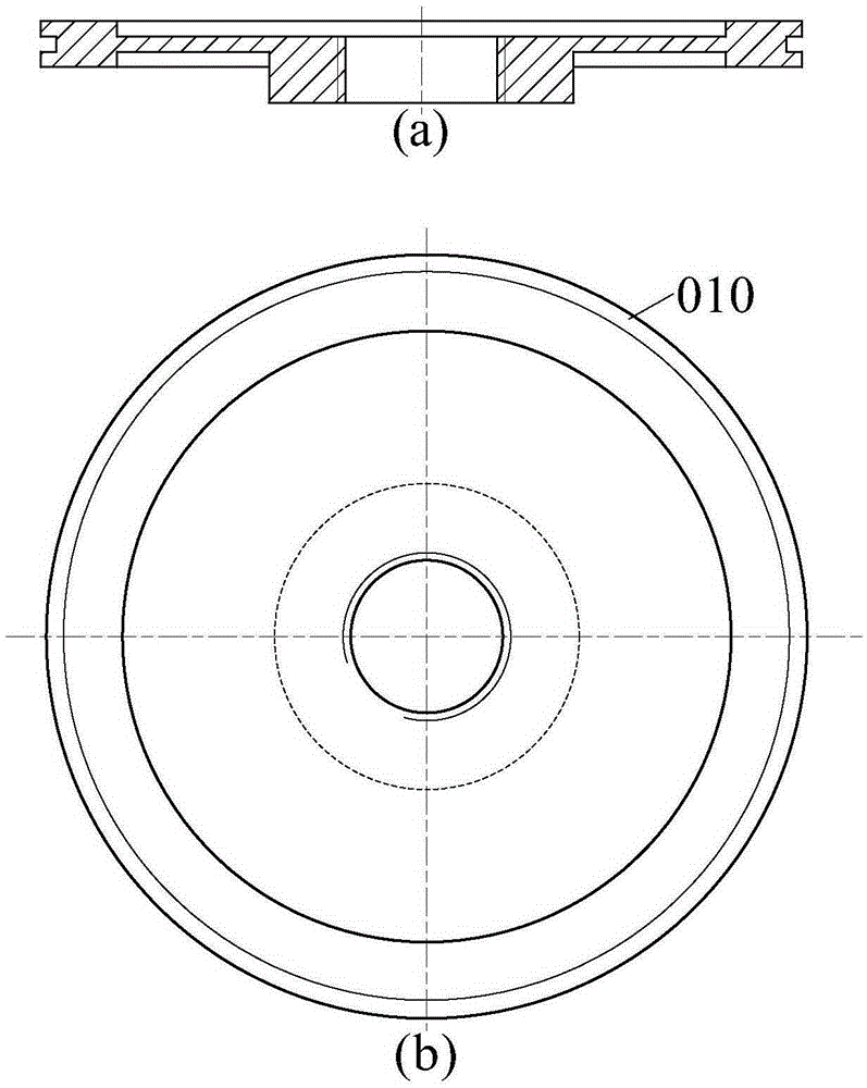
[0055] A rotating ultrasonic excitation device, see Figure 1 to Figure 10 , the rotating ultrasonic excitation device mainly includes: disc stator 010, stator support 020, lock nut 030, stator clamping device 040, piezoelectric vibrator 050, piezoelectric vibrator clamping device 060, piezoelectric vibrator locking device 070 , T-slot fastener 080 and base 090.
[0056] Wherein, the disc-shaped stator 010 is threadedly connected with the stator support 020 and locked by a locking nut 030 ; the stator clamping device 040 clamps along the edge of the disc-shaped stator 010 and is locked by the first set screw 021 . The lower end of the stator clamping device 040 is connected to the piezoelectric vibrator 050 through bolts, and the piezoelectric vibrator 050 is inserted into the piezoelectric vibrator clamping device 060 . The piezoelectric vibrator clamping device 060 is inserted into the piezoelectric vibrator locking device 070 and locked by the second set screw 071 . The p...
Embodiment 2
[0069] The embodiment of the present invention takes figure 1 The rotary ultrasonic excitation device shown is taken as an example to discuss the influence of the number of piezoelectric vibrators 050 and its topological configuration on the vibration of the disc stator 010. Figure 11 For the calculation model, the number of groups of piezoelectric vibrators 050 is P, and the number of each group is N s . The coordinate system {o, r, θ} is fixed on the disc stator 010, where the origin o is located at the geometric centroid of the disc stator 010, and the polar axis r passes through the geometric centroid of the first piezoelectric vibrator 050 in the first group , θ is the polar angle, is the ith (i=1, 2, 3,...N s ) a piezoelectric vibrator.
[0070] (1) Group symmetrical piezoelectric components
[0071] Because the piezoelectric vibrators 050 are grouped symmetrically along the circumferential direction of the disk-shaped stator 010, and the piezoelectric vibrators 0...
Embodiment 3
[0113] The embodiment of the present invention provides 6 piezoelectric vibrator excitation devices, the working wave number is 2, the grouping number P is 2, the harmonic order is 1, the space-time phase ratio is 2, and the piezoelectric vibrators 050 in the group are evenly distributed. And works in d33 mode. Figure 12 The relationship between the angle between adjacent piezoelectric vibrators 050 and the amplitude is given. The included angle of the piezoelectric vibrator 050 in the group is π / 4, and the response of the disc stator 010 is a backward traveling wave The concrete connection process of each component in this embodiment is:
[0114](1) Connect the six piezoelectric vibrators 050 to the disk-shaped stator 010 through the stator clamping device 040; (2) insert the piezoelectric vibrators 050 into the piezoelectric vibrator clamping device 060; (3) insert the piezoelectric vibrator clamping device 060 is inserted into the piezoelectric vibrator locking device 0...
PUM
 Abstract
Description
Claims
Application Information
 - R&D
- Intellectual Property
- Life Sciences
- Materials
- Tech Scout
- Unparalleled Data Quality
- Higher Quality Content
- 60% Fewer Hallucinations
Browse by: Latest US Patents, China's latest patents, Technical Efficacy Thesaurus, Application Domain, Technology Topic, Popular Technical Reports.
© 2025 PatSnap. All rights reserved.Legal|Privacy policy|Modern Slavery Act Transparency Statement|Sitemap|About US| Contact US: help@patsnap.com


