High-frequency electronic ballast

An electronic ballast and high-frequency technology, which is applied in the field of high-frequency electronic ballasts, can solve problems such as product inconsistency, easily damaged ballasts, and lamp life reduction, and achieve product consistency and reliability improvement , prolong the lamp life, the effect of constant power output

Active Publication Date: 2016-01-20
长河智造(山东)电子科技有限公司
View PDF6 Cites 0 Cited by
  • Summary
  • Abstract
  • Description
  • Claims
  • Application Information

AI Technical Summary

Problems solved by technology

[0002] The high-frequency electronic ballast of the IR215X self-oscillating MOS driver has been widely used, and its application circuits have been published in a large number of IR company’s technical literature and various magazines, but there is a maximum The shortcoming is that the power of lamps with different tube pressure drops varies by 20%-40%, the product power is not consistent, and it is easy to damage the ballast. For example, for 150W sodium lamp tubes, the standard for lamp tube voltage in China is 80V~ 120V, the world is roughly the same value. The power of the high-frequency electronic ballast driven by IR215X differs by more than 30%. Such a large power difference indicates that the product has no consistency. When the power is 151W, the tube power of the 100V tube voltage can reach 176W, and the tube power of the 120V tube can reach 200W, which is easy to damage the tube, reduce the reliability of the ballast, and reduce the life of the lamp. The use of IR215X and similar ICs has lost confidence, which has affected the product quality and reputation of ballast manufacturers. However, the circuit of IR215X is simple and the finished product is low, so many researchers and manufacturers continue to research and invest, and a large number of products and thesis, but without exception all fail on this issue

Method used


Image

  • High-frequency electronic ballast
  • High-frequency electronic ballast
  • High-frequency electronic ballast

Examples


Embodiment Construction

[0011] The following will clearly and completely describe the technical solutions in the embodiments of the present invention with reference to the accompanying drawings in the embodiments of the present invention. Obviously, the described embodiments are only some, not all, embodiments of the present invention. Based on the embodiments of the present invention, all other embodiments obtained by persons of ordinary skill in the art without making creative efforts belong to the protection scope of the present invention.

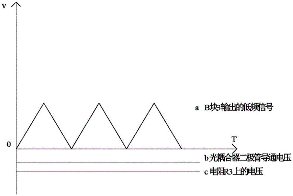
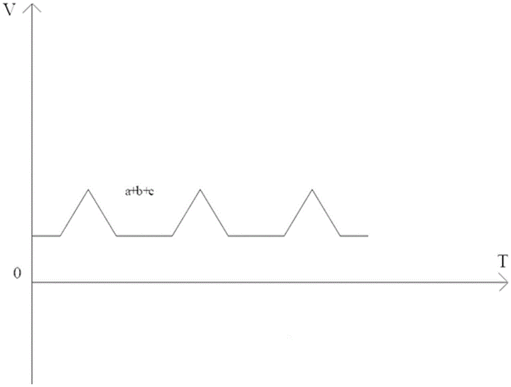
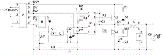
[0012] see figure 1 , in an embodiment of the present invention, a high-frequency electronic ballast includes an optocoupler V1, a low-frequency oscillator B, a diode D1, a capacitor C2, a resistor R1, a resistor R6, a diode D4, a starter C and a potentiometer R2, The optocoupler V1 separates the low-frequency oscillator B from the main oscillator IC circuit. The output pin 3 of the low-frequency oscillator B is connected to one end of the resistor R1, and the...


PUM


Abstract

The invention discloses a high-frequency electronic ballast, which comprises an optical coupler V1, a low-frequency oscillator B, a diode D1, a capacitor C2, a resistor R1, a resistor R6, a diode D4, a starter C and a potentiometer R2, wherein the low-frequency oscillator B is separated from a main oscillator IC circuit by the optical coupler V1; an output pin 3 of the low-frequency oscillator B is connected with one end of the resistor R1; the other end of the resistor R1 is connected with one end of the potentiometer R2 and a positive pole of a photodiode of the optical coupler V1; and the other end of the potentiometer R2 is connected with one end of a resistor R3 and is connected with a ground end of a power supply A. According to the high-frequency electronic ballast, only two devices are added under the condition of keeping the simple circuit and the low cost of an IR215X driver; consistent power of different tube voltage drop lamps is achieved according to an ingenious and novel design of the circuit; improvement of a constant power output and the product consistency and reliability is achieved by 80-120V tube voltage drop lamps; and the lifetime of the lamps is prolonged.

Description

technical field [0001] The invention relates to a ballast, in particular to a high-frequency electronic ballast. Background technique [0002] The high-frequency electronic ballast of the IR215X self-oscillating MOS driver has been widely used, and its application circuits have been published in a large number of IR company’s technical literature and various magazines, but there is a maximum The shortcoming is that the power of lamps with different tube pressure drops varies by 20%-40%, the product power is not consistent, and it is easy to damage the ballast. For example, for 150W sodium lamp tubes, the standard for lamp tube voltage in China is 80V~ 120V, the world is roughly the same value. The power of the high-frequency electronic ballast driven by IR215X differs by more than 30%. Such a large power difference indicates that the product has no consistency. When the power is 151W, the tube power of the 100V tube voltage can reach 176W, and the tube power of the 120V tub...

Claims


Application Information

Patent Timeline
Patent Type & Authority Applications(China)
IPC IPC(8): H05B41/288
Inventor 杜宏时
Owner 长河智造(山东)电子科技有限公司
Why Eureka
Try Eureka