A bidirectional longitudinal-torsional compound vibration device

A technology of compound vibration and longitudinal torsion, which is applied in the direction of fluid using vibration, can solve the problems of poor interchangeability and inability to realize rapid tool change, etc., and achieve the effect of simple vibration form, simple power supply form and good interchangeability

Inactive Publication Date: 2018-09-11
HARBIN INST OF TECH
View PDF4 Cites 0 Cited by
  • Summary
  • Abstract
  • Description
  • Claims
  • Application Information

AI Technical Summary

Problems solved by technology

[0003] In order to solve the problem that the existing vibrating device has poor interchangeability and cannot realize rapid tool change, the present invention further proposes a bidirectional longitudinal-torsion compound vibrating device

Method used


Image

  • A bidirectional longitudinal-torsional compound vibration device
  • A bidirectional longitudinal-torsional compound vibration device
  • A bidirectional longitudinal-torsional compound vibration device

Examples


specific Embodiment approach 1

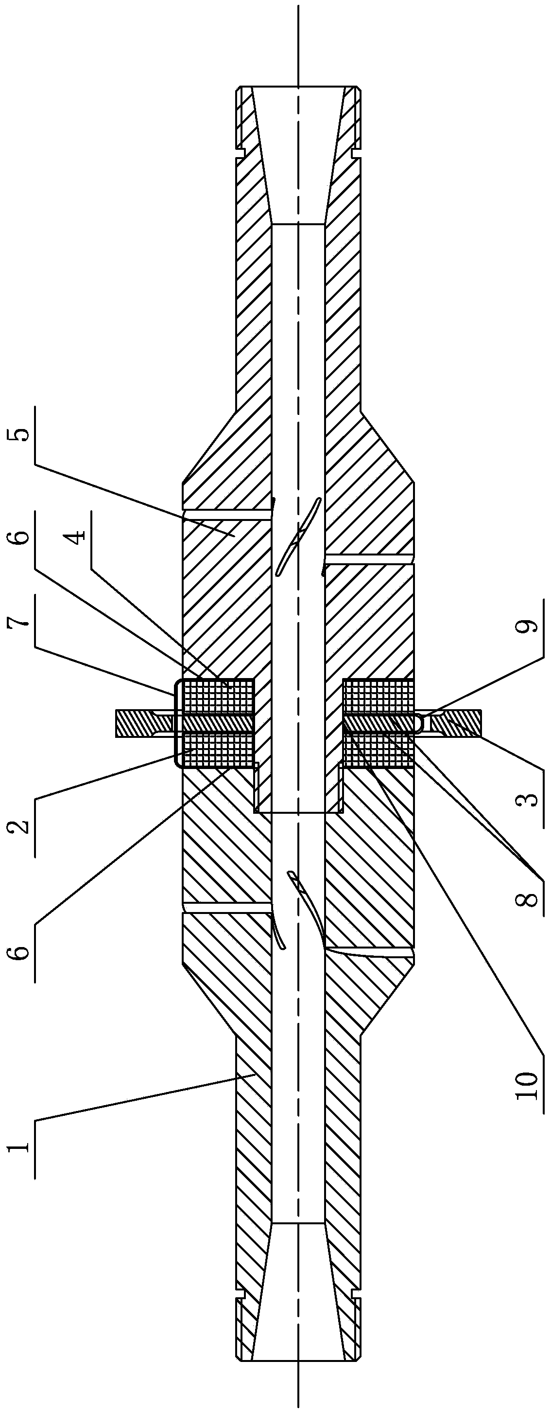
[0016] Specific implementation mode one: combine figure 1 This embodiment is described. A bidirectional longitudinal-torsional compound vibration device described in this embodiment includes a front cover 1, a first annular piezoelectric ceramic 2, a mounting plate 3, a second annular piezoelectric ceramic 4, a rear cover 5, a first electrical One end of the front cover 1 and one end of the back cover 5 are plugged in, and the connection between the front cover 1 and the back cover 5 is sequentially fitted with a first ring-shaped pressure ring from one end of the front cover 1 to one end of the back cover 5. The electric ceramic 2 , the mounting plate 3 , and the second annular piezoelectric ceramic 4 , the first electrode end and the second electrode end are arranged symmetrically at the joint between the front cover 1 and the rear cover 5 . The front cover 1 and the rear cover 5 are fastened with epoxy glue, and the first annular piezoelectric ceramic 2 and the second annul...

specific Embodiment approach 2

[0019] Specific implementation mode two: combination figure 1 Describe this embodiment, the first electrode end of a kind of two-way vertical torsional compound vibration device described in this embodiment includes two first electrodes 6 and a first electrode connection copper sheet 7, the end surface of one end of the front cover 1 is connected with the first ring A first electrode 6 is arranged between the piezoelectric ceramics 2, and a first electrode 6 is arranged between the end face of one end of the back cover 5 and the second annular piezoelectric ceramic 4, and the two first electrodes 6 are connected to copper via the first electrodes. Slice 7 is connected. Other components and connections are the same as those in the first embodiment.

specific Embodiment approach 3

[0020] Specific implementation mode three: combination figure 1 To illustrate this embodiment, the second electrode end of a bidirectional longitudinal-torsional compound vibration device described in this embodiment includes two second electrodes 8 and a second electrode connection copper sheet 9, the first annular piezoelectric ceramic 2 and the mounting plate A second electrode 8 is provided between 3, a second electrode 8 is provided between the second annular piezoelectric ceramic 4 and the mounting board 3, and the two second electrodes 8 are connected through a second electrode connection copper sheet 9.

[0021] The first electrode connection copper sheet 7 and the second electrode connection copper sheet 9 respectively connect all positive electrodes and all negative electrodes of the piezoelectric ceramics together, and the negative electrodes are connected to the front cover 1 and the rear cover 2 and grounded. Other components and connections are the same as those ...


PUM


Abstract

The invention relates to a vibration device, in particular to a bi-directional longitrorse combined vibration device. The problems that an existing vibration device is simple in vibration mode and limited in application are solved. The bi-directional longitrorse combined vibration device comprises a front cover, a first annular piezoelectric ceramic part, an installation plate, a second annular piezoelectric ceramic part, a rear cover, a first electrode end and a second electrode end, wherein one end of the front cover and one end of the rear cover are connected in an inserted mode; the first annular piezoelectric ceramic part, the installation plate and the second annular piezoelectric ceramic part are sequentially installed in the connecting position of the front cover and the rear cover from one end of the front cover to one end of the rear cover in a sleeving mode, and the first electrode end and the second electrode end are symmetrically arranged in the connecting position of the front cover and the rear cover. The bi-directional longitrorse combined vibration device is applied to the field of ultrasonic machining.

Description

technical field [0001] The invention relates to a vibrating device, in particular to a bidirectional longitudinal-torsional compound vibrating device, which belongs to the field of ultrasonic processing. Background technique [0002] In recent years, ultrasonic vibration processing has developed very rapidly, mainly because it shows advantages that traditional processing does not have in the processing of hard and brittle materials and some high-strength materials, mainly including the reduction of cutting force, the reduction of cutting temperature, and the quality of cutting surface. Good and small tool wear, etc. At the same time, ultrasonic vibration machining can make the workpiece or tool show rigidity enhancement and other effects when processing weak stiffness structures, so ultrasonic vibration machining is widely used. At present, the elliptical ultrasonic vibration turning technology, ultrasonic vibration drilling technology and rotary ultrasonic machining technol...

Claims


Application Information

Patent Timeline
Patent Type & Authority Patents(China)
IPC IPC(8): B06B1/06
Inventor 陈时锦吴陈军孙雪
Owner HARBIN INST OF TECH
Why Eureka
Try Eureka