A lamination molding apparatus

A technology of layered modeling and inert gas, which is applied in the directions of manufacturing auxiliary devices, processing and manufacturing, and manufacturing tools, etc., can solve the problems of difficulty in maintaining the concentration of inert gas and displacement of body moldings.

Active Publication Date: 2016-01-27
SODICK CO LTD
View PDF5 Cites 17 Cited by
  • Summary
  • Abstract
  • Description
  • Claims
  • Application Information

AI Technical Summary

Problems solved by technology

[0007] However, as in Patent Document 1, if a different type of gas is supplied from the inert gas in the chamber, it becomes more difficult to maintain the concentration of the inert gas in the chamber.
In addition, if the gas of different temperature is supplied, the temperature in the chamber changes, which may cause unnecessary displacement of the machine body or the molded object during the molding process.

Method used


Image

  • A lamination molding apparatus
  • A lamination molding apparatus
  • A lamination molding apparatus

Examples


Embodiment Construction

[0024] Embodiments of the present invention will be described below using the drawings. Various characteristic matters shown in the embodiments shown below may be combined with each other.

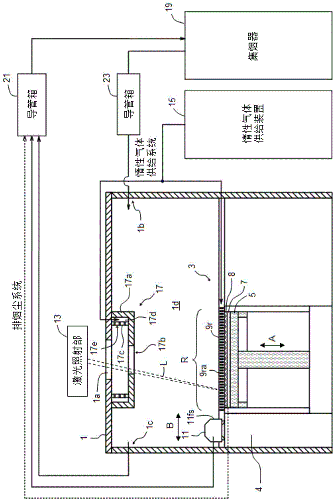
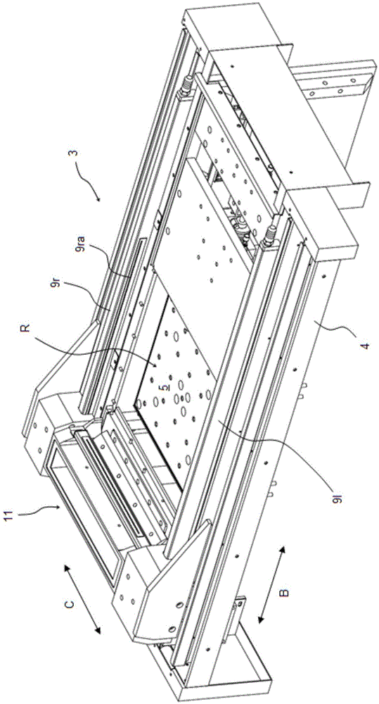
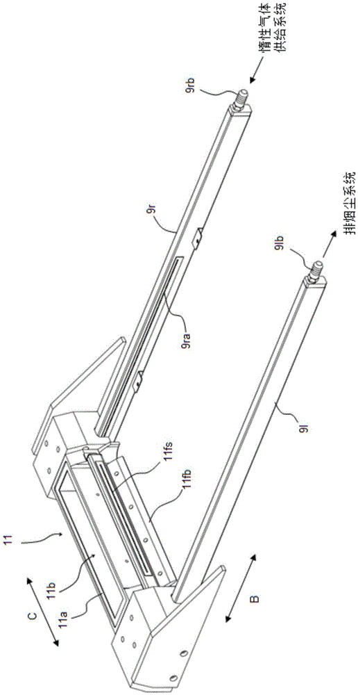
[0025] Such as Figure 1 ~ Figure 2 As shown, a powder layer forming device 3 is provided in a cavity 1 in a layered molding device according to an embodiment of the present invention. The powder layer forming device 3 is provided with: a base 4 having a modeling area R; a coating head 11 configured to be arranged on the base 4 and movable in a horizontal 1-axis direction (direction of arrow B); The components 9r, 9l are arranged on both sides of the styling area R along the moving direction of the coating head 11. In the modeling area R, there is a set that can be used in the up and down direction ( figure 1 Arrow A direction) moving modeling table 5. When a stacked molding device is used, a molding plate 7 is arranged on the molding table 5, and a material powder layer 8 is formed on...


PUM


Abstract

An improved lamination molding apparatus which can maintain the inert gas environment in the chamber as well as remove the fume swiftly and efficiently away from the optical pathway of the laser beam, is provided. According to the invention, the lamination molding apparatus is provided which comprises a cavity body, a smoke diffusion portion installed on the inner side of the top portion of the cavity body, an inertia gas diffusion portion and an inertia gas supply path. The cavity body comprises a molding space covering a molding area, and is filled with inertia gasses at a preset concentration. The smoke diffusion portion comprises a housing which has an opening portion which will not shut off laser irradiating towards the molding area. The inertia gas supply path enables the housing to be filled with gases which are of the same kind with the inertia gases in the molding space. The inertia gasses are jet out from the opening portion. A laminar flow of the inertia gases forms along the irradiation path of the laser, and is discharged from the irradiation path.

Description

technical field [0001] The present invention relates to a stack molding device. Background technique [0002] In the metal powder sintering lamination method (light modeling) by laser, when a metal material powder is irradiated with a laser and sintered, a characteristic fume called fume is generated. When the cavity is filled with smoke and dust, the laser may be blocked, and the laser with the required energy cannot reach the sintered part. [0003] The current optical molding machine (sintered lamination molding device) for molding metal objects is generally structured to operate so that the material powder is dispersed in a cavity filled with an inert gas (usually nitrogen) and irradiated with laser light. [0004] In order to stably irradiate the laser beam, it is necessary to keep the concentration of the inert gas in the chamber constant, so clean inert gas is supplied while exhausting the dirty inert gas in the chamber. The management of the inert gas in the chambe...

Claims


Application Information

Patent Timeline
Patent Type & Authority Applications(China)
IPC IPC(8): B22F3/105B33Y30/00
CPCB29C64/153B33Y30/00B29C64/268B29C64/371Y02P10/25B22F12/38B22F12/49B22F10/32B22F10/28B22F12/41B22F10/77
Inventor 新家一朗村中胜隆川田秀一冈崎秀二
Owner SODICK CO LTD
Why Eureka
Try Eureka