
Maintaining pad having high-precision flatness

A technology for retaining pads and average diameters, applied in electrical components, work carriers, semiconductor/solid-state device manufacturing, etc. Excellent buffer layer, increased strength and abrasion resistance, improved overall compressibility and compression recovery effect

Inactive Publication Date: 2016-01-27
大元化成株式会社
View PDF7 Cites 0 Cited by
  • Summary
  • Abstract
  • Description
  • Claims
  • Application Information

AI Technical Summary

Problems solved by technology

In this case, when the size of the foam is increased to improve cushioning, the size of the foam expands to near the surface, resulting in a decrease in strength
When the cushioning property is low, the variation of the support stress of the object to be polished will become large, so that the amount of polishing to the polished surface will be uneven, thus resulting in uneven thickness of the polished product, that is, resulting in flatness of the product bad degree problem
[0004] On the contrary, when the cushioning property is high, although the problem that the polishing amount of the surface of the polished product is partially uneven can be solved because the change in the supporting stress of the polished object is small, the strength and wear resistance are deteriorated, resulting in retention The pad itself is partially detached, thus finally causing a problem that the flatness of the surface is deteriorated

Method used


Image

  • Maintaining pad having high-precision flatness
  • Maintaining pad having high-precision flatness
  • Maintaining pad having high-precision flatness

Examples


Embodiment 1

[0027] Compression recovery of polyurethane foam pads according to the content ratio of methylenediphenyldiisocyanate (MDI) to polyol

[0028] After the molding of the polyurethane foam pad using the resin composition in which the content ratio of MDI to the polyol in the resin composition was increased, the compressibility and the compression recovery thereof were respectively measured.

[0029] The results are shown in Table 1. As the content of MDI relative to polyol increases, the compressibility decreases significantly but the compression recovery increases.

[0030] Table 1:

[0031] MDI / Polyol(%)

Embodiment 2

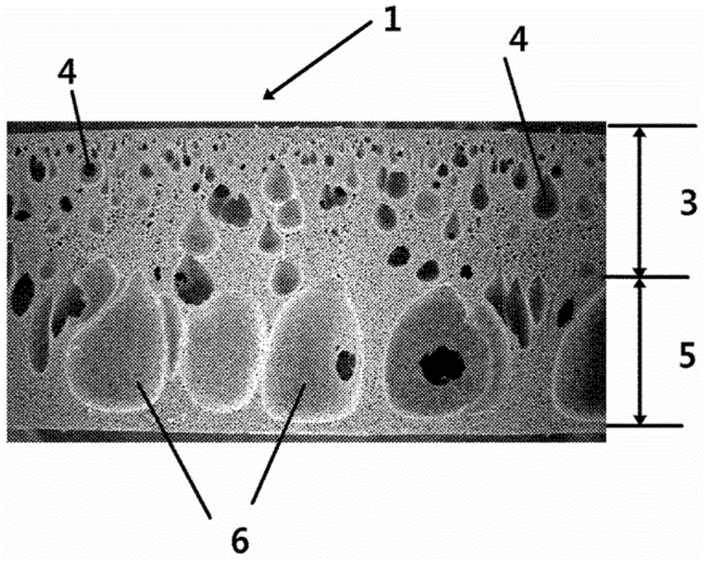
[0033] The surface solidification speed of the resin is increased and the urethane foam pad 1 is molded using a resin polymerized by a prepolymer method that increases the content of hard segments of the polymerized resin. As a result, minute foams are formed within 50% of the entire thickness of the urethane foam pad 1, and giant foams are formed in a region of 60 to 90% of the entire thickness ( figure 1 ).

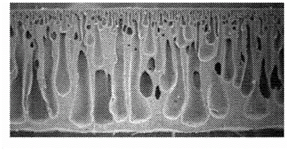
[0034] In contrast, polyurethane foam mats molded using a resin polymerized by a one-step foaming method showed such figure 2 Foam shape and arrangement shown.

Embodiment 3

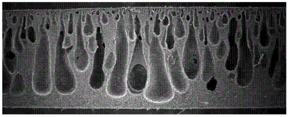
[0036] In the case of adding water within 2% to the resin composition, it was shown as image 3 porosity shown. In contrast, the second comparative example using a general hydrophilic surfactant showed such Figure 4 The foam shape shown.

[0037] Explanation of symbols

[0038] 1: Holding pad

[0039] 3: Upper supporting layer

[0040] 4: micro foam

[0041] 5: Lower buffer layer

[0042] 6: huge foam


PUM


Abstract

The present invention relates to a maintaining pad for supporting and fixing a polished product on a platform when the flat-plate polished product such as a glass substrate and a wafer is polished. The maintaining pad is characterized in that an upper supporting layer (3) in which small expanding foams (4) with small diameters are distributed is formed by crossing 50% area of a polyurethane pad, and a lower buffer layer (5) located at the area within the range from 60% to 90% of the thickness of the polyurethane pad has huge expanding foams (6) of which the diameters are relatively dozens of times larger than the diameters of the small expanding foams (4) of the upper supporting layer (3), thus the integral compressibility and compress recovery ratio can be improved, therefore, high-precision flatness is achieved.

Description

technical field [0001] The present invention relates to a holding pad for supporting and fixing a polished product to a table when polishing a flat-plate type polished product such as a glass substrate, a wafer, or the like. Background technique [0002] Since products such as glass substrates for LCDs, semiconductor wafers, etc. require high precision in thickness, their surfaces are generally polished precisely using polishing pads or polishing cloths. As described above, when a product to be polished is surface-polished, a holding pad that supports the product to be polished on the table of the polishing apparatus is used. Such holding pads are required to have high-precision flatness for high-precision surface polishing of polished products. [0003] As disclosed in Patent Document 1 below, conventional retaining pads are generally foamed across the entirety in the thickness direction. In this case, when the size of the foam is increased in order to improve the cushion...

Claims


Application Information

Patent Timeline
IPC IPC(8): B24B37/27H01L21/304
Inventor 姜东烨崔洪德安炯一徐呈旼张容源朴寅慧
Owner 大元化成株式会社
Learn More