Workpiece transport device

A technology for conveying devices and workpieces, applied in the directions of conveyor objects, transportation and packaging, furnace components, etc., can solve the problems of increasing the upper and lower height of the conveying chamber, increasing the mechanical strength, and changing the upper and lower positions, and achieves compactness, restraint The effect of increasing the size and reducing the moment load

Inactive Publication Date: 2016-01-27
DAIHEN CORP
View PDF7 Cites 3 Cited by
  • Summary
  • Abstract
  • Description
  • Claims
  • Application Information

AI Technical Summary

Problems solved by technology

As a result, the vertical position of the transport path of the workpiece becomes higher, and the vertical height of the transfer chamber has to be increased, etc., leading to an increase in the size and cost of the processing equipment.
[0006] In addition, since the weight of the front end portion of the arm being rotated incre

Method used


Image

  • Workpiece transport device
  • Workpiece transport device
  • Workpiece transport device

Examples


Example Embodiment

[0042] Hereinafter, a preferred embodiment of the present invention will be specifically described with reference to the drawings.
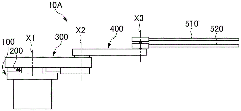
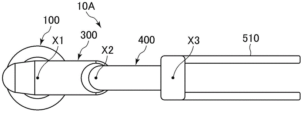
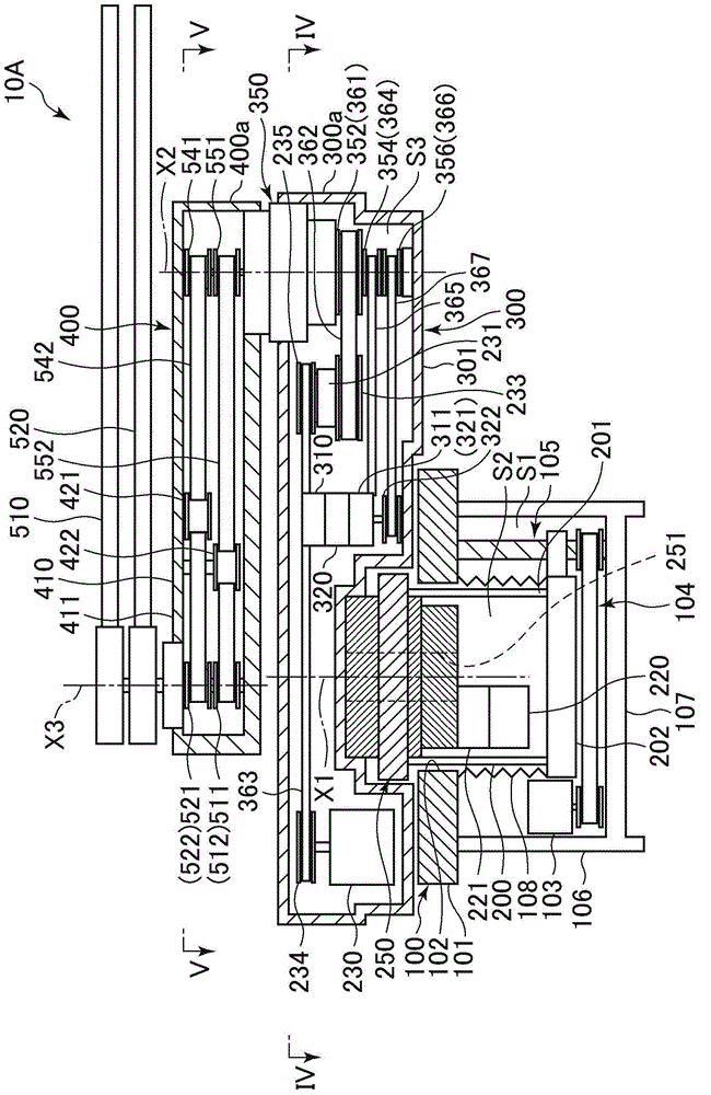
[0043] Figure 1 to Figure 6 The work conveying device 10A of the first embodiment of the present invention is shown. The workpiece conveying device 10A includes a fixed base 100, a supporting base 200, a supporting arm 300, a hand holding arm 400, and two hands 510 and 520. The workpiece conveying device 10A is installed in a conveying chamber in a processing system performed in a vacuum environment, for example.

[0044] Such as image 3 As shown in the figure, the fixed base 100 accommodates and holds the supporting base 200 in a liftable manner. The support base 200 has an upper part protruding from the opening 102 of the top plate 101 provided in the fixed base 100, and is supported so as to be liftable by a vertical guide (not shown). In addition, the support base 200 is raised and lowered by the ball screw mechanism 105 capable of transmittin...


PUM


Abstract

The invention aims to shorten the moment of the vertical dimension of a swing arm relative to an arm root and provides a workpiece transport device. The workpiece transport device comprises a support base, a support arm in rotatable connection with a main rotation axis relative to the support base, a hand retaining arm in rotatable connection with an elbow joint axis relative to the support arm, a hand in rotatable connection with the elbow joint axis relative to the hand retaining arm, a support arm motor used for driving the support arm to rotate around the support base and arranged in the support base, a hand retaining arm motor used for driving the hand retaining arm to rotate around the support arm, a hand motor used for driving the hand to rotate around the hand retaining arm and arranged in the support arm, a joint axis coaxially arranged together with the elbow joint axis and used for driving the hand retaining arm to rotate relative to the support arm, a transmission shaft used for transmitting the power for driving the hand to rotate, a first reduction mechanism arranged in the support base and used for reducing the output of the support arm motor, and a second reduction mechanism arranged in the support arm and used for reducing the output of the hand retaining arm motor.

Description

technical field [0001] The present invention relates to a workpiece conveying device suitable for conveying thin plate-shaped workpieces such as glass substrates and wafers in a vacuum environment. Background technique [0002] Such as Figure 11 As shown, in the processing system in which the processing chambers are arranged radially around the transfer chamber, the workpiece transfer device arranged in the transfer chamber for transferring workpieces between the processing chambers can advance the workpiece in the radial direction when viewed from above. It only needs to be moved, so, for example, as disclosed in Patent Document 1, it is possible to use an articulated arm-type transport device in which a parallel linkage mechanism (parallel linkage) is combined. Such a conveyance device can maintain the posture of the hand holding the workpiece with a small power source due to the function of the parallel link mechanism, and can move the workpiece forward in a plan view. ...

Claims


Application Information

Patent Timeline
IPC IPC(8): B65G47/90B65G49/06B65G49/07
Inventor 冈本健太郎井浦惇
Owner DAIHEN CORP
Why Eureka
Try Eureka