
Method for removing crystalline salt as well as design method and application thereof

A crystallized salt removal technology, applied in the direction of cleaning methods and appliances, chemical instruments and methods, mechanical equipment, etc., can solve the problems of incomplete flushing of clogged objects, clogging, and unreasonable planning of crystallized salt treatment methods, etc.

Active Publication Date: 2016-01-27
CATECH TECH
View PDF3 Cites 3 Cited by
  • Summary
  • Abstract
  • Description
  • Claims
  • Application Information

AI Technical Summary

Problems solved by technology

Flushing methods include continuous or irregular random flushing. The continuous flushing method is to flush the blocked pipes with water. The advantage of this is that the flushing effect is better, but continuous flushing with desalinated water will seriously waste water resources.
The irregular random flushing method is to release water for flushing when it is found that there are more ammonium salts or metal ions in the liquid oil product or when the equipment or pipelines are blocked. Incomplete flushing of blockages, especially for slightly soluble and water-insoluble substances, causes wear and blockage of equipment and pipelines, so refineries often replace heat exchangers after reactors and heat exchange tubes of air coolers
In addition, even if washing is carried out, it is a late-morning practice. The previous intermediate product already contains impurities such as crystal salts and metal salts, which cannot be remedied when entering the next process, and there are too few water injection points, resulting in incomplete removal of crystal salts.
Therefore, the existing technology does not have a reasonable plan for the treatment of crystallized salt in the hydrogenation unit and the pipeline, and cannot meet the requirements of the slurry bed hydrogenation reaction for the removal of blockages

Method used


Image

  • Method for removing crystalline salt as well as design method and application thereof

Examples


Embodiment Construction

[0025] In order to further illustrate the technical content of the present invention, it will be described in conjunction with the accompanying drawings and specific embodiments.

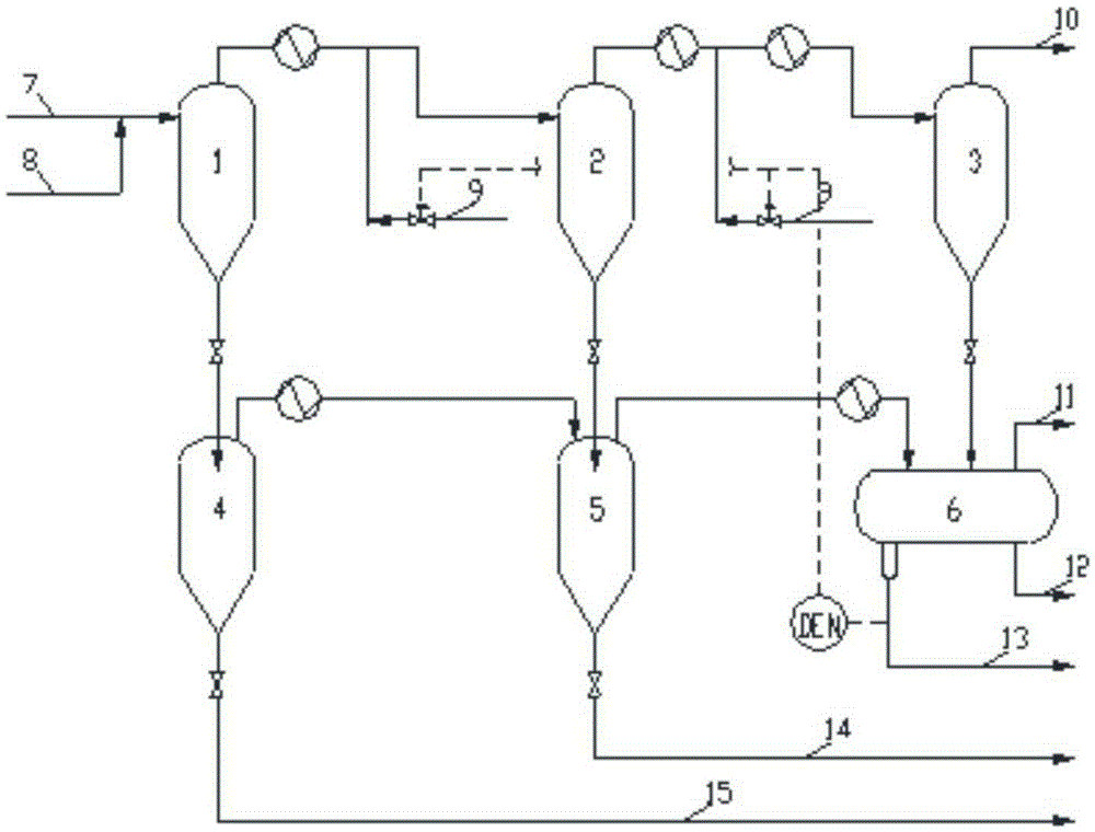
[0026] like figure 1 As shown, this embodiment is a method for removing blockages in the high-pressure separation system, and the separation system belongs to the separation process in the slurry bed hydrogenation reaction process. The high-pressure separation system consists of six different separators, which are high-temperature and high-pressure separator 1, medium-temperature and high-pressure separator 2, normal-temperature and high-pressure separator 3, low-pressure and high-temperature separator 4, low-pressure and medium-temperature separator 5, and low-pressure normal-temperature separator 6. The normal temperature and low pressure separator 6 is placed horizontally, and the remaining separators are placed vertically. In order to remove blockages such as crystalline salt in slurry bed reac...


PUM


Abstract

The invention provides a method for removing crystalline salt as well as a design method and an application thereof. According to the method, at least one concentration detector is arranged in a wastewater outlet pipeline of the last stage of a separator, the concentration of blocking substances gathered in water injection positions after water injection and washing is detected, the variety of the blocking substances is determined, then the amount of water injected to each water injection position is controlled to be 50-1,000 times of water demand of saturated concentration of the blocking substances, and the water injection positions are located on pipelines between a reactor and separators and/or pipelines between separators. The method for removing the crystalline salt is applied to equipment and pipelines in a slurry bed hydrogenation process, the problem that a large quantity of byproducts such as crystalline substances and the like exist in hydrogenation products is solved, the content of the blocking substances is monitored in real time, the blocking substances in the hydrogenation equipment and the pipelines are removed in time, and the content of nitrogen and heavy metal in hydrogenation products and separated intermediate products of liquid oil is reduced.

Description

technical field [0001] The invention relates to a method for removing crystallized salt in hydrogenation equipment and pipelines, its design method and application, and can also remove blockages such as metal salts and other by-products, belonging to the fields of petrochemical and coal chemical industries. Background technique [0002] In recent years, research on slurry bed hydrogenation technology for heavy oil (including residual oil, catalytic oil slurry, deoiled pitch and coal tar), oil-coal mixing and direct coal liquefaction technology (both core processes are slurry bed hydrogenation) The main reason is that the slurry bed hydrogenation process can effectively utilize heavy oil resources and coal resources, remove impurities such as sulfur, nitrogen and heavy metals in raw materials, and increase the yield and quality of light oil at the same time, thereby improving the profitability of processing enterprises. economic benefits. However, since the reaction material...

Claims


Application Information

Patent Timeline
Patent Type & Authority Applications(China)
IPC IPC(8): C10G75/00C02F9/10
CPCB08B9/027C10G75/00F16L58/00
Inventor 李苏安邓清宇王坤朋
Owner CATECH TECH
Learn More