
Induction heating device for cutter shaft quenching

An induction heating device and cutter shaft technology, applied in heat treatment furnaces, heat treatment equipment, furnace types, etc., can solve problems affecting production costs and production efficiency, high scrapping rate of cutter shaft quenching, lack of protection, etc., to achieve improved Ease of use, overcoming quenching cracks, and avoiding the effect of excessive temperature

Active Publication Date: 2018-06-26
常州宝隆冶金设备制造有限公司
View PDF9 Cites 0 Cited by
  • Summary
  • Abstract
  • Description
  • Claims
  • Application Information

AI Technical Summary

Problems solved by technology

[0002] The material of the cutter shaft is usually 42CrMo. The surface requires high wear resistance and high hardness. The hardness needs to reach 55HRC. There is a keyway on the shaft body, and a solid copper bar is usually embedded in the keyway, and the width of the outer surface of the copper bar is slightly larger than the width of the notch to shield the induced current. However, in the prior art, the machined copper bar is manually The bar is embedded in the keyway by knocking, it is difficult to achieve a tight fit, and the fit with the circular keyway is even worse, and because the copper bar is heated and expanded during the quenching process, it is easy to be squeezed out of the keyway. The protective effect is still very easy to cause quenching cracks. Last year, the company’s cutter shaft quenching scrap rate was as high as 30%, which seriously affected the production cost and production efficiency.

Method used


Image

  • Induction heating device for cutter shaft quenching
  • Induction heating device for cutter shaft quenching
  • Induction heating device for cutter shaft quenching

Examples


Embodiment Construction

[0026] The present invention will be further described below in conjunction with the accompanying drawings and specific embodiments.

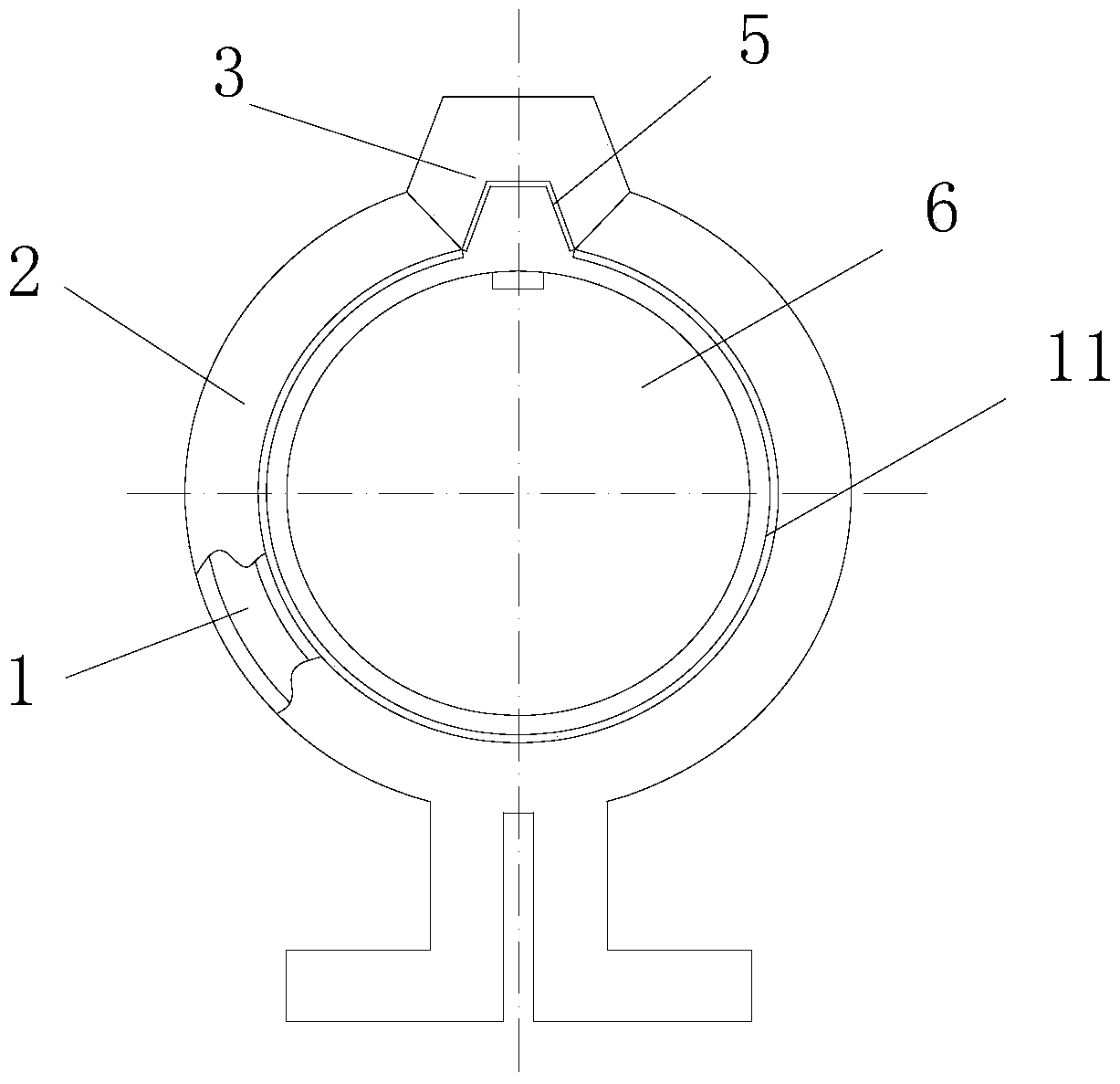
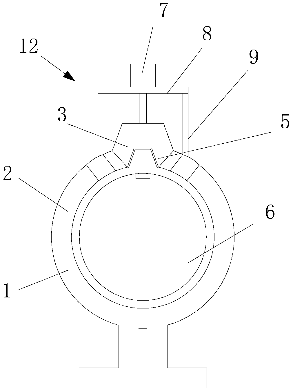
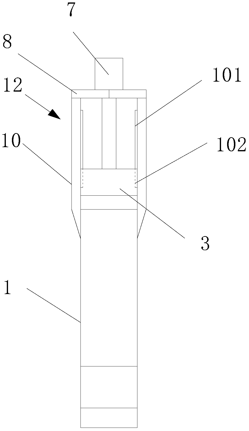
[0027] Such as figure 1 The shown induction heating device for cutter shaft quenching includes a hollow carrier 2, an induction coil 1 is arranged inside the carrier, and a bending part 3 is provided on the carrier 2, and the bending part 3 is protruding The structure of the carrier can be arc-shaped, trapezoidal or other shapes that can increase the distance between the bending part and the workpiece. The surface of the bending part 4 near the workpiece is provided with a magnetizer 5, and the The bending part adjusts the distance between the induction coil and the workpiece, thereby adjusting the induction temperature at the workpiece corresponding to the bending part, that is, controlling the quenching temperature of the workpiece corresponding to the bending part, and the further set magnetizer can control the induction coil The magnetic l...


PUM


Abstract

The invention belongs to quenching equipment, and in particular, relates to an induction heating device for quenching a surface of a cutter shaft provided with a key slot. The induction heating device for quenching the cutter shaft comprises a hollow bearing body, wherein an induction coil is arranged in the bearing body. The induction heating device is characterized in that a bending part is arranged on the bearing body; and a magnetizer is arranged on the surface of one side, near a workpiece, of the bending part. The invention provides the induction heating device which can adjust a gap between the bending part and the workpiece and is provided with the magnetizer on one side surface, near the workpiece, of the bending part.

Description

technical field [0001] The invention belongs to quenching equipment, in particular to an induction heating device for surface quenching of a cutter shaft provided with key grooves. Background technique [0002] The material of the cutter shaft is usually 42CrMo. The surface requires high wear resistance and high hardness. The hardness needs to reach 55HRC. There is a keyway on the shaft body, and a solid copper bar is usually embedded in the keyway, and the width of the outer surface of the copper bar is slightly larger than the width of the notch to shield the induced current. However, in the prior art, the machined copper bar is manually The bar is embedded in the keyway by knocking, it is difficult to achieve a tight fit, and the fit with the circular keyway is even worse, and because the copper bar is heated and expanded during the quenching process, it is easy to be squeezed out of the keyway. The protective effect is still very easy to cause quenching cracks. Last yea...

Claims


Application Information

Patent Timeline
Patent Type & Authority Patents(China)
IPC IPC(8): C21D1/10C21D9/22
CPCY02P10/25
Inventor 崔利嘉许波林王俊军祝庆丰
Owner 常州宝隆冶金设备制造有限公司
Learn More