Liquid conveying device

A technology for conveying devices and liquids, applied in water supply devices, waterway systems, drainage structures, etc., can solve the problems of complex anti-blocking alarm devices, inability to eliminate toxic gases, and inability to detect water inlet blockages, etc., to prevent sludge deposition. Effect

Inactive Publication Date: 2016-01-27
TAIZHOU SHENGHE WATER TREATMENT EQUIP MFG CO LTD
View PDF5 Cites 2 Cited by
  • Summary
  • Abstract
  • Description
  • Claims
  • Application Information

AI Technical Summary

Problems solved by technology

In the prior art, pumping stations include civil pumping stations and prefabricated pumping stations. In the control of prefabricated pumping stations, there are only control settings for toxic gases inside the wellbore, and some toxic gases cannot be eliminated.
And the anti-blocking alarm device is more complicated and cannot detect the blockage of the water inlet

Method used


Image

  • Liquid conveying device

Examples


Embodiment Construction

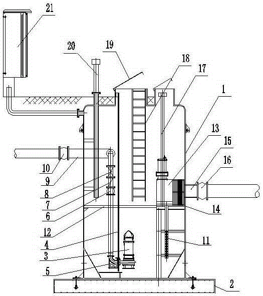
[0013] like figure 1 As shown, a liquid conveying device includes a wellbore 1, the wellbore 1 is fixed on a base 2, and a submersible sewage pump 3 is arranged on one side of the base 2, and the submersible sewage pump 3 is fixed on a submersible sewage pump guide rod and a lifting chain 4, The upper end of the guide rod of the submersible sewage pump and the lifting chain 4 are fixed on the top of the shaft 1; the submersible sewage pump 3 is sequentially connected to the valve flexible joint 6, check valve 7, gate valve 8, outlet pipe 9, and outlet pipe flexible joint 10 through the coupling base 5; the base 2 The other side is equipped with a liquid level control system and a detection system device 11. The working platform 12 on the upper part of the control system and detection system device 11 is located in the middle of the shaft 1; A fancy grid 14 is connected to the side of the type grid 13, and is connected with the flexible joint 16 of the water inlet pipe outside ...


PUM


Abstract

The invention relates to a liquid conveying device. The liquid conveying device comprises a shaft; the shaft is fixed on a base; a submersible sewage pump is arranged above at one side of the base; the submersible sewage pump is fixed on a submersible sewage pump guide rod and a lifting chain; the submersible sewage pump is connected with a valve flexible joint, a check valve, a gate valve, a water outgoing pipe and a water outgoing pipe flexible joint sequentially through a coupling seat; the other side of the base is provided with a liquid level control system, a detection system device, a crush type grid, a flower type grid, a water incoming pipe and a water incoming pipe flexible joint; the upper outlet of the shaft is provided with a top cover; a maintenance ladder is arranged in the shaft; the shoulder of the shaft is provided with a gas exhausting pipe; and the exterior of the shaft is provided with an electric appliance control system device. According to the liquid conveying device of the invention, a conical bottom is designed, so that deformation can be avoided assuredly, the area of the bottom can be minimized; the gas exhausting pipe is adopted to eliminate some toxic gases in the shaft; and an anti-blocking range can be checked through monitoring whether self shutdown of the water pump begins exceeding set time.

Description

technical field [0001] The invention relates to the technical field of mechanical equipment, in particular to a liquid conveying device. Background technique [0002] Liquid conveying device, pumping station is one of them. In the prior art, pumping stations include civil pumping stations and prefabricated pumping stations. In the control of prefabricated pumping stations, there is only a control setting for the toxic gas inside the wellbore, and part of the toxic gas cannot be eliminated. And the anti-blocking alarm device is more complicated and cannot detect the blocking situation of the water inlet. Contents of the invention [0003] In order to overcome the above technical problems, the present invention provides a device with a wide range of anti-blocking and investigation, and a device for reducing part of the poisonous gas generated at the bottom. The technical scheme adopted is as follows: [0004] A liquid conveying device, comprising a shaft, the shaft is fixe...

Claims


Application Information

Patent Timeline
Patent Type & Authority Applications(China)
IPC IPC(8): E03F5/22
Inventor 戴文平
Owner TAIZHOU SHENGHE WATER TREATMENT EQUIP MFG CO LTD
Why Eureka
Try Eureka