Three-layer tubing string injection device

An oil tubing string and a tubing string technology are applied in the field of a three-layer tubing string dispensing device, which can solve problems such as large lifting and fishing workload, and achieve the effects of improving water injection efficiency, strong practicability, and simple overall structure.

Active Publication Date: 2017-11-07
SHANDONG MOLONG PETROLEUM MACHINERY
View PDF5 Cites 0 Cited by
  • Summary
  • Abstract
  • Description
  • Claims
  • Application Information

AI Technical Summary

Problems solved by technology

[0005] 1. The oil jacket separate injection process can only inject two oil layers at the same time
[0006] 2. Single-pipe water injection in layers, up to five layers of water injection, only one layer can be injected with water at a time, and when the other layer is injected with water, the tool needs to be lifted, and the lifting workload is heavy
[0007] 3. Multi-tube layered water injection can be injected at the same time, but according to the current string structure, only two layers can be injected separately

Method used


Image

  • Three-layer tubing string injection device
  • Three-layer tubing string injection device
  • Three-layer tubing string injection device

Examples


Embodiment 1

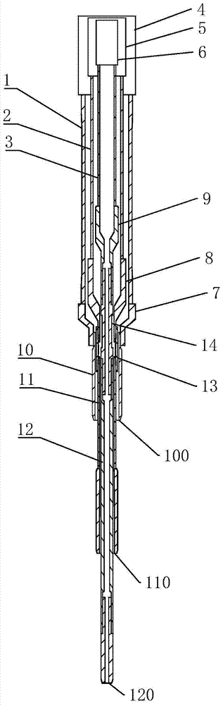
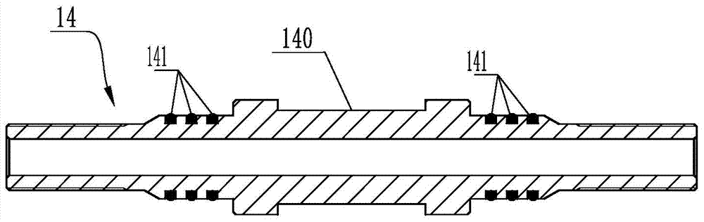
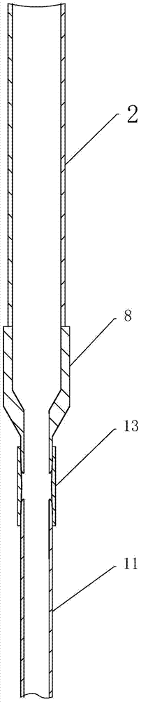
[0032] Such as Figure 1 to Figure 4 Commonly shown in the above, a three-layer tubing string dispensing device includes an outer layer string 1, an intermediate layer string 2 and an inner layer string 3;

[0033] One end of the outer layer pipe string 1 is provided with an outer layer connection assembly, the other end of the outer layer pipe string 1 is connected to the outer layer water injection pipe 10 through the outer layer reducing joint 7, and one end of the middle layer pipe string 2 is provided with an intermediate layer connection assembly, The other end of the middle layer pipe string 2 is connected to the middle layer water injection pipe 11 through the middle layer reducing joint 8, one end of the inner layer pipe string 3 is provided with an inner layer connection assembly, and the other end of the inner layer pipe string 3 is passed through the inner layer reducing joint 9 connect the inner layer water injection pipe 12. The above-mentioned outer layer conne...

Embodiment 2

[0064] The structure of this embodiment is basically the same as that of Embodiment 1, the difference lies in the size change of the above-mentioned pipe column, water injection pipe, and water injection port at the end of the water injection pipe, as follows:

[0065] Outer tubing string 1: use tubing with an outer diameter of 96.84mm and a large inner diameter, with an inner diameter of 85mm;

[0066] The outer gap connecting hoop 4 adopts a 3-1 / 2EU small gap oil pipe coupling, and the outer diameter of the outer gap connecting hoop is 116mm;

[0067] Outer water injection pipe 10: oil pipe with an outer diameter of 58 mm and an inner diameter of 47 mm. The outer water injection pipe 10 is connected to the outer pipe column through an outer variable diameter joint, and the inner diameter of the water injection port 100 at its end is 47 mm.

[0068] Middle layer tubing string 2: use tubing with an outer diameter of 62mm and an inner diameter of 54mm;

[0069] 2-3 / 8NU small-g...

Embodiment 3

[0077] The structure of this embodiment is basically the same as that of Embodiment 1, the difference lies in the size change of the above-mentioned pipe column, water injection pipe, and water injection port at the end of the water injection pipe, as follows:

[0078] Outer tubing string 1: use tubing with an outer diameter of 92mm and an inner diameter of 79mm;

[0079] The outer gap connecting hoop 4 adopts a 3-1 / 2EU small gap oil pipe coupling, and the outer diameter of the outer gap connecting hoop is 105mm;

[0080] The outer layer water injection pipe 10: the outer diameter is 54 mm, the inner diameter is 43 mm, connected to the outer layer pipe string 1 through the outer layer variable diameter joint 7, and the inner diameter of the water injection port 100 at the end is 43 mm.

[0081] Middle layer tubing string 2: oil pipe with an outer diameter of 59.53mm and an inner diameter of 49mm;

[0082] 2-3 / 8NU small-gap tubing couplings are adopted for the middle layer gap...


PUM


Abstract

The invention relates to a three-layer tubing string dispensing device, which comprises an outer layer pipe string, an intermediate layer pipe string and an inner layer pipe string; one end of the outer layer pipe string is provided with an outer layer connecting assembly, and One end of the pipe string is provided with an intermediate layer connection assembly, and one end of the inner layer pipe string is provided with an inner layer connection assembly; the other end of the outer layer pipe string is connected to the outer layer water injection pipe through the outer layer reducing joint, and the middle layer The other end of the layer pipe string is connected to the middle layer water injection pipe through the intermediate layer reducing joint, and the other end of the inner layer pipe string is connected to the inner layer water injection pipe through the inner layer reducing joint. The oil layer of the three-layer oil well can be injected separately at the same time, and the water injection efficiency of the oil well can be improved. The overall structure is simple, easy to manufacture and install, and has strong practicability.

Description

technical field [0001] The invention belongs to the technical field of oil layer water injection devices, in particular to a three-layer oil pipe column injection device. Background technique [0002] After the oil well is put into development, as the production time increases, the energy of the oil layer itself will be continuously consumed, resulting in a continuous drop in oil layer pressure, an increase in viscosity, a significant reduction in crude oil production, and even shutdown, resulting in a large amount of dead oil left underground that cannot be recovered. In order to make up for the underground deficit caused by the extraction of crude oil, maintain or increase the pressure of the reservoir, achieve high and stable oil production, and obtain a high recovery rate, it is necessary to inject water into the oil field. [0003] For the currently exploited oil fields, the oil layers of oil wells can be summarized as follows. Some oil wells have only one oil layer, an...

Claims


Application Information

Patent Timeline
Patent Type & Authority Patents(China)
IPC IPC(8): E21B17/18E21B43/20
Inventor 张云三张洪海国焕然黎新春张松江梁永强
Owner SHANDONG MOLONG PETROLEUM MACHINERY
Why Eureka
Try Eureka