Liquid crystal display panel and spacer assembly thereof
A liquid crystal display panel and spacer technology, which is applied in nonlinear optics, instruments, optics, etc., can solve the problems of weak anti-dynamic pressure, large deformation of PS under pressure, and easy crushing, so as to increase the pressure resistance effect of ability
- Summary
- Abstract
- Description
- Claims
- Application Information
AI Technical Summary
Problems solved by technology
Method used
Image

Examples
Embodiment 1
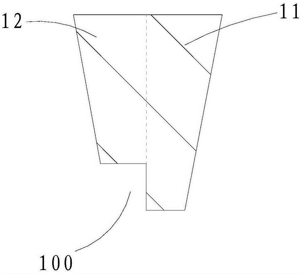
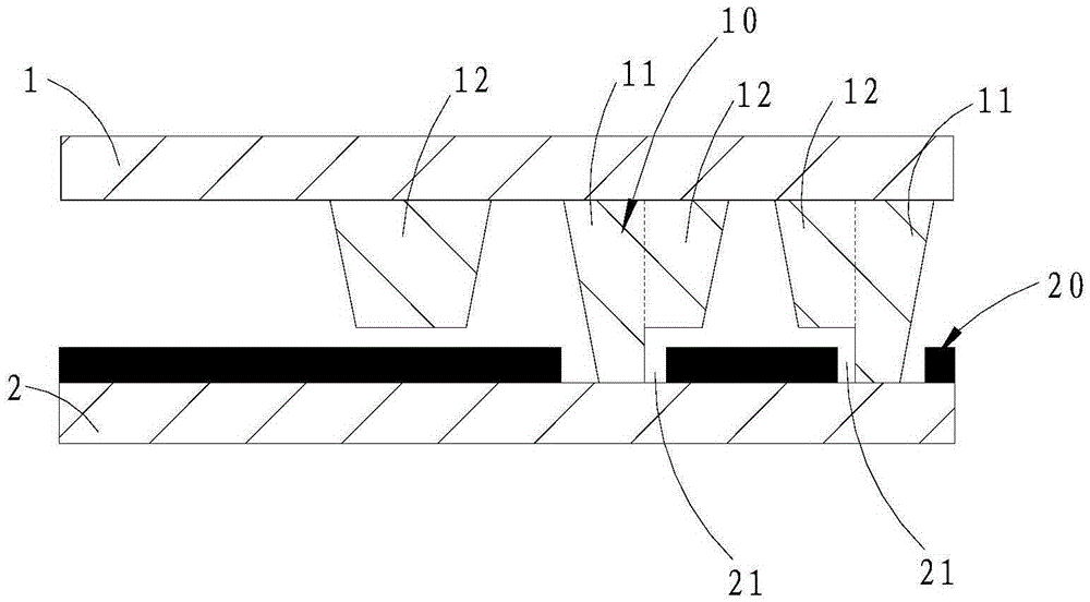
[0035] refer to figure 1 and figure 2 , The spacer assembly of this embodiment includes an upper spacer 10 and a lower spacer 20, which are fixed on the inner surfaces of the upper substrate 1 and the lower substrate 2, respectively. Wherein, the upper spacer 10 includes a combination (not shown) formed by the first spacer part 11 and the second spacer part 12 with a height difference, and the lower spacer 20 is formed on the lower spacer 20 to cooperate with the upper spacer 10. Pressing surface (not shown). It can be understood that, in other embodiments, the upper spacer 10 and the lower spacer 20 can also be fixed on the lower substrate 2 and the upper substrate 1 respectively.
[0036] Such as figure 1 , in this combination, the end portion of the first spacer part 11 protrudes from the end face of the second spacer part 12, thereby forming the side surface of the first spacer part 11 and the second spacer part at the free end of the combination. The transitional ste...
Embodiment 2
[0049] Such as Figure 4 and Figure 5 As shown, different from Embodiment 1, the upper spacer 10 of the spacer assembly of this embodiment further includes a main spacer post 3 of a cylindrical structure fixed on the inner surface of the upper substrate 1 .
[0050] Preferably, the height of the main spacer column 3 is the same as the height of the first spacer part 11 in the composite structure, and the main spacer column 3 corresponds to the concave part on the pressing surface.
[0051] Specifically, after the installation is completed, the ends of the main spacer column 3 and the first spacer part 11 in the combined structure are all pressed on the pressing surface, and the first spacer part 11 in the combined structure plays a role in contact with the main spacer. The spacer 3 has the same function, and both act as the main spacer together, while the second spacer part 12 is suspended. The sum of the contact density or distribution density of the first spacer part 11 i...
Embodiment 3
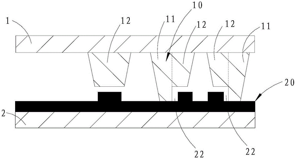
[0055] Such as Figure 6 and Figure 7 As shown, the difference from Embodiment 1 is that the distance between the end surface of the second spacer part 12 and the pressing surface of the separate column structure of the spacer assembly in this embodiment is greater than that of the second spacer in the assembly The distance between the portion 12 and the pressing surface makes the upper spacer 10 of this embodiment have three kinds of contact distances with the pressing surface, which has better compression resistance and wider range of high and low temperature LCMargin.
[0056] Preferably, the same as in Embodiment 1, the end faces of the second spacer part 12 of the single column structure and the second spacer part 12 in the combined structure of this embodiment are also flush, so that the upper spacer 10 as a whole also has only two heights, and can be manufactured using a half-grayscale mask process, which can simplify the manufacturing process and reduce manufacturing...
PUM
 Abstract
Description
Claims
Application Information
 - Generate Ideas
- Intellectual Property
- Life Sciences
- Materials
- Tech Scout
- Unparalleled Data Quality
- Higher Quality Content
- 60% Fewer Hallucinations
Browse by: Latest US Patents, China's latest patents, Technical Efficacy Thesaurus, Application Domain, Technology Topic, Popular Technical Reports.
© 2025 PatSnap. All rights reserved.Legal|Privacy policy|Modern Slavery Act Transparency Statement|Sitemap|About US| Contact US: help@patsnap.com