Process and device for cement clinker production

A technology of cement bricks and brick furnaces, applied in the field of manufacturing cement bricks and devices, to achieve the effect of increasing production capacity

Inactive Publication Date: 2016-01-27
HOLCIM
View PDF3 Cites 2 Cited by
  • Summary
  • Abstract
  • Description
  • Claims
  • Application Information

AI Technical Summary

Problems solved by technology

However, this is opposed to the fact that the cost

Method used


Image

  • Process and device for cement clinker production
  • Process and device for cement clinker production

Examples


Embodiment Construction

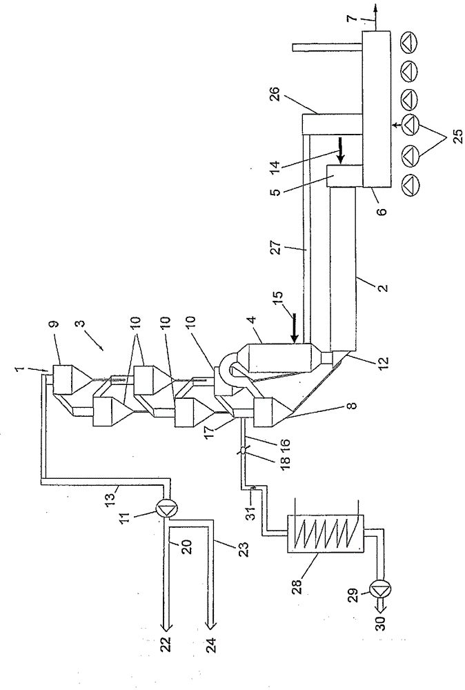
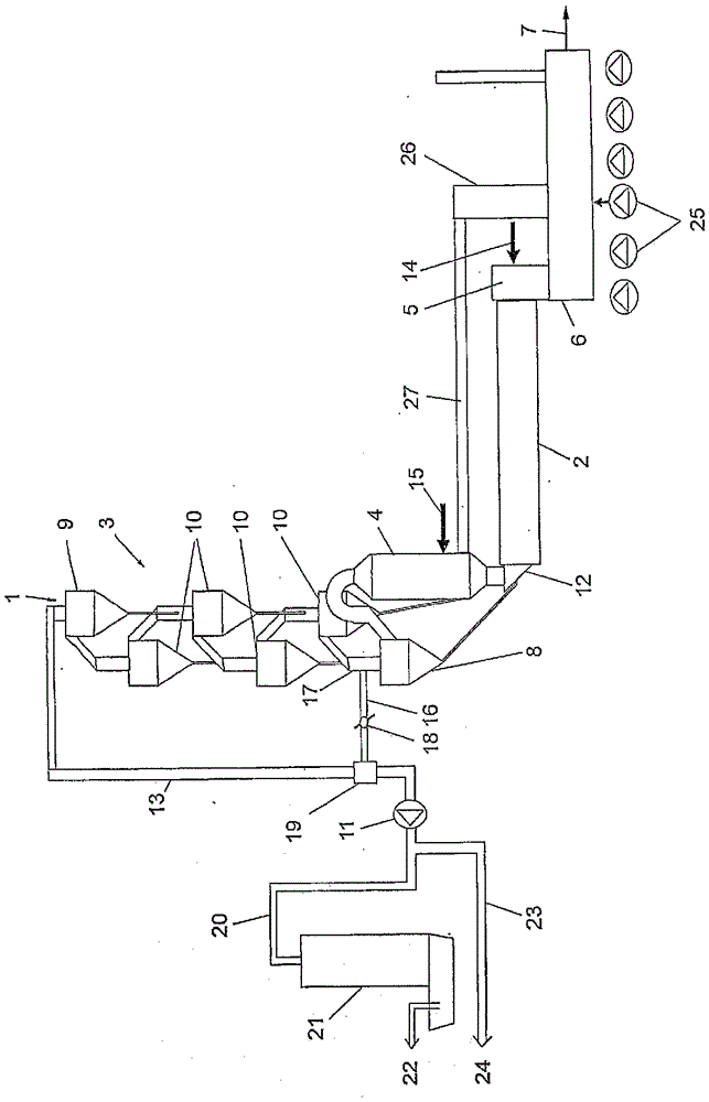
[0026] exist figure 1 A cement brick production plant is shown in , in which the raw material powder fed at the point indicated schematically with 1 is preheated in the preheater 3 in the countercurrent flow of the hot exhaust gases of the brick furnace 2 and heated in the calciner 4 Calcined. The bricks leave the brick oven 2 at the point indicated at 5 and are cooled in a brick cooler 6 . The cooled bricks leave the brick cooler 6 at the point indicated at 7 .

[0027] The preheater 3 can have one or more preheating sections. A section is shown in the drawing. This section has a plurality of vortex-suspended air heat exchangers connected in sequence, wherein the first suspended air heat exchanger is indicated by 8, the last suspended air heat exchanger is indicated by 9 and the suspended air heat exchange between them is The device is represented by 10. The furnace blower 11 generates the required negative pressure, whereby the furnace exhaust gas flowing out on th...


PUM


Abstract

In a cement clinker production process in which raw mix is preheated with use of the hot exhaust gases from a clinker furnace in a preheater (3) and the preheated raw mix, optionally calcined in a calciner (4), is fired in the clinker furnace (2) to give clinker, wherein the preheater (3) comprises at least one train from a plurality of cyclone flotation gas heat exchangers (8, 9, 10) through which the furnace exhaust gas passes in succession and in which the raw mix is preheated in stages, a substream of the furnace exhaust gas is diverted in such a way that only a residual stream of the furnace exhaust gas is utilized for preheating the raw mix.

Description

technical field [0001] The invention relates to a method for the manufacture of cement bricks, wherein raw material powder is preheated in a preheater with hot exhaust gases of a brick furnace and the preheated and optionally calcined raw material powder is fired in a brick furnace bricks, wherein the preheater comprises at least one section consisting of a plurality of vortex-suspended air heat exchangers through which the furnace exhaust gas flows sequentially, in which the raw material powder is pre-staged hot. [0002] Furthermore, the invention relates to a cement brick production plant comprising a brick furnace to which a brick cooler is connected at the output-side end of the brick furnace and a preheater and possibly a calciner connected at the feed-side end of the brick furnace , wherein the preheater comprises at least one section composed of a plurality of vortex-suspension air heat exchangers which can be sequentially passed by the furnace exhaust gas along th...

Claims


Application Information

Patent Timeline
IPC IPC(8): C04B7/43
CPCC04B7/434C04B7/475F27D17/004C04B2290/20F27B7/2016C04B7/43Y02P40/121C04B7/432C04B7/44C04B7/4407F26B23/00F27B7/20
Inventor U.加斯塞
Owner HOLCIM
Why Eureka
Try Eureka