Decelerating clutch and washing machine
A technology of deceleration clutch and deceleration wheel, applied in the field of washing machine, can solve the problem of waste of bottom space, and achieve the effect of shortening the overall height, reducing the overall height and reducing the volume
- Summary
- Abstract
- Description
- Claims
- Application Information
AI Technical Summary
Problems solved by technology
Method used
Image
Examples
Embodiment 1
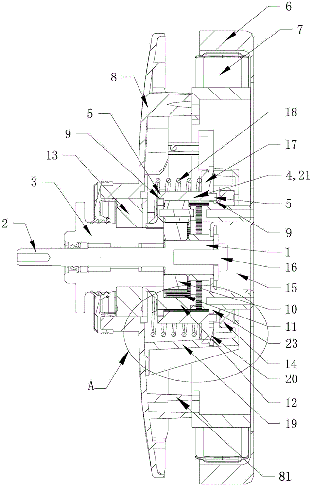
[0043] In this embodiment, the clutch device is at least partly arranged on the periphery of the reduction device, so that the projections of the clutch device and the reduction device on the axis of the reduction clutch at least partially coincide.
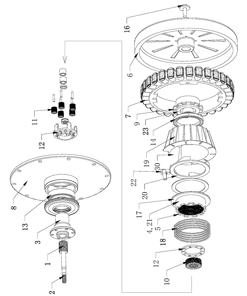
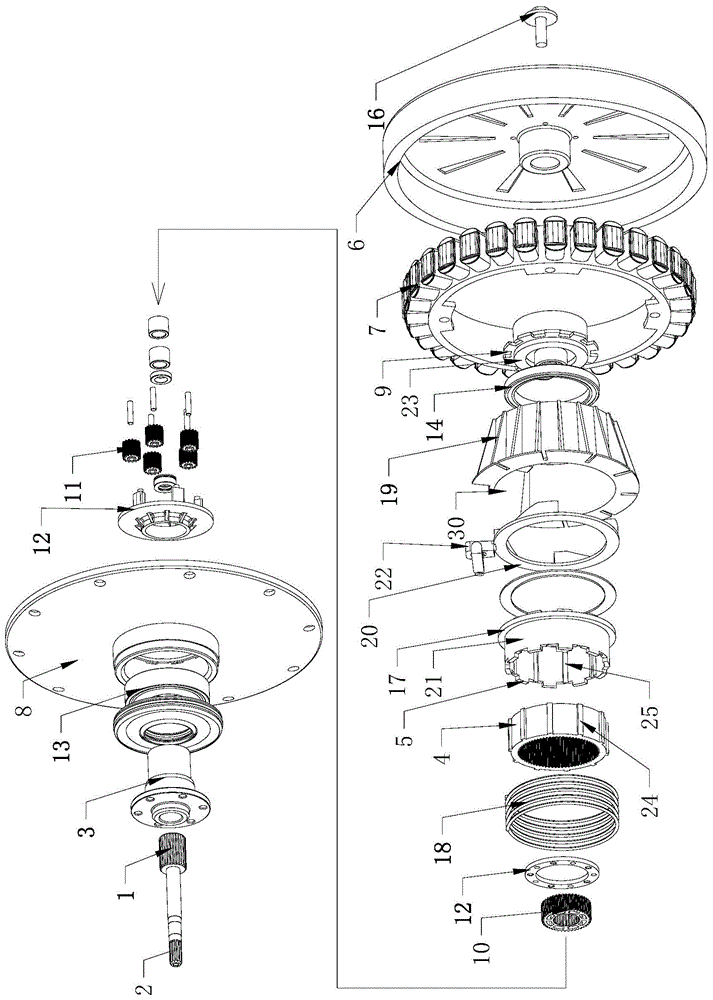
[0044] In this embodiment, the clutch device includes a clutch sleeve 21 that can move axially and a clutch driving device that drives the clutch sleeve 21 to move axially. The clutch shaft sleeve 21 slides up and down driven by the clutch drive device, and the output shaft 2 and the output shaft sleeve 3 switch between different output states.
[0045] In this embodiment, the clutch sleeve 21 is fitted on the outer periphery of the reduction gear, so that the projection of the clutch sleeve 21 and the reduction gear on the axis of the reduction clutch at least partially coincides. Through the above setting, the height space of the original clutch sleeve 21 is saved, and the overall height of the deceleration clutch is reduced, s...
Embodiment 2
[0047] In this embodiment, the reduction device includes a reduction gear train and an inner ring gear engaged with the reduction gear train; the reduction gear train and / or the inner ring gear are at least partially disposed in the hollow portion of the motor. One end of the input shaft is connected with the rotor of the motor, and the other end is respectively connected with the output shaft sleeve and the output shaft through the reduction gear train.
[0048] The different output states of the reduction clutch are determined by the structure of the reduction gear train inside the reduction gear, and the present invention only introduces one of the reduction gear trains; 10 revolving planetary gear 11, and the ring gear 4 meshing with the planetary gear 11; the planetary gear 11 is meshed with the center gear 10 and the ring gear 4 respectively, so that the planetary gear 11 produces a revolution around the axis of the center gear 10; the planetary gear 11 And / or the center...
Embodiment 3
[0054] In this embodiment, the inner wall of the clutch bushing 21 is provided with meshing teeth that mesh with the planetary gear 11, so that the clutch bushing 21 constitutes the ring gear 4 of the reduction gear. The clutch sleeve 21 can be engaged with the planetary gear 11 and can also slide relative to the planetary gear 11 along the axis. Under the action of the clutch driving device, the clutch sleeve 21 is moved in the axial direction to control the output shaft 2 and the output sleeve 3 to switch between different output states.
[0055] In this embodiment, when the clutch sleeve 21 slides in the axial direction, it is necessary to keep the clutch sleeve 21 meshed with at least part of the planetary gears 11 in the reduction gear. Preferably, the clutch sleeve 21 is composed of a straight tube sleeve, and the inner wall of the straight tube sleeve is evenly distributed with meshing teeth meshing with the planetary gear 11 . The meshing teeth extend from one end of ...
PUM
 Abstract
Description
Claims
Application Information
 - R&D
- Intellectual Property
- Life Sciences
- Materials
- Tech Scout
- Unparalleled Data Quality
- Higher Quality Content
- 60% Fewer Hallucinations
Browse by: Latest US Patents, China's latest patents, Technical Efficacy Thesaurus, Application Domain, Technology Topic, Popular Technical Reports.
© 2025 PatSnap. All rights reserved.Legal|Privacy policy|Modern Slavery Act Transparency Statement|Sitemap|About US| Contact US: help@patsnap.com


