Tubing Float Valve and Combined Method of Tubing Blowout Prevention, Gas Lift and Fracturing in Underbalanced Well Completion

An under-balanced, oil-pipe technology, which is used in earth-moving drilling, wellbore/well components, and wellbore/well valve devices, etc., can solve the problems of oil-prevention pipes that cannot be established smoothly, complicated operations, and low production efficiency.

Active Publication Date: 2018-10-09
CNPC XIBU DRILLING ENG
View PDF5 Cites 0 Cited by
  • Summary
  • Abstract
  • Description
  • Claims
  • Application Information

AI Technical Summary

Problems solved by technology

[0003] The present invention provides a tubing float valve and an underbalanced well completion downhole tubing blowout prevention, gas lift and fracturing combined method, which overcomes the shortcomings of the above-mentioned prior art , which can effectively solve the problems of the existing under-balanced technology in the anti-oil pipe internal injection that cannot successfully establish the internal and external passages of the oil pipe, and has potential safety hazards, poor reservoir protection effect, cumbersome operation, long operation period, and low production efficiency.

Method used


Image

  • Tubing Float Valve and Combined Method of Tubing Blowout Prevention, Gas Lift and Fracturing in Underbalanced Well Completion

Examples


Embodiment 1

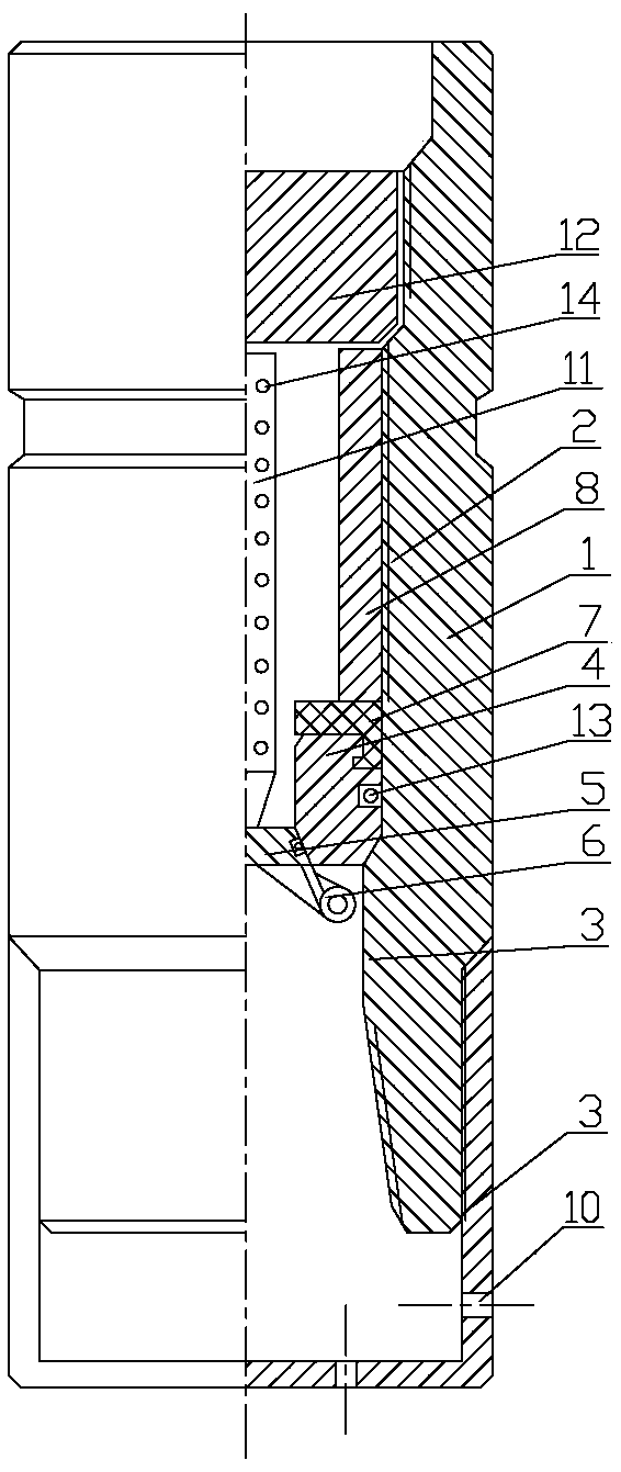
[0019] Embodiment 1, as attached figure 1 As shown, the multifunctional tubing floating hoop includes a body 1, a valve seat 4, a valve 5, a torsion spring 6, a sealing ring 7, a top wire 8 and a fishing basket 9; The reduced upper ring platform 2 and the lower ring platform 3 have a valve seat 4 whose outer diameter matches the inner diameter of the upper ring platform 2 on the upper end surface of the lower ring platform 3. The valve seat 4 is an annular cylinder, and the inner diameter of the valve seat 4 is less than The inner diameter of the lower ring platform 3, the lower inner wall of the valve seat 4 is a conical ring surface with a small upper part and a larger lower part. The end face and the lower end face of the valve 5 are fixedly installed together and the valve 5 is sealed in the lower part of the valve seat 4. On the upper end face of the valve seat 4, there is a seal ring 7 whose outer diameter matches the inner diameter of the upper ring platform 2. A top w...

Embodiment 2

[0022] Embodiment 2, as preferred embodiment 1, as attached figure 1 Shown, the upper end face of lower ring platform 3 is the conical ring surface that is up big and the bottom is small, and the bottom of valve seat 4 is the cone truncated that matches with the conical ring surface of lower ring platform 3 upper surface. When the valve seat 4 is on the upper end surface of the lower ring platform 3, the cone ring surface on the upper end surface of the lower ring platform 3 matches the cone platform at the bottom of the valve seat 4, which can provide better installation stability and sealing.

Embodiment 3

[0023] Embodiment 3, as the preferred embodiment of the above, as attached figure 1 As shown, the upper end surface of the upper ring platform 2 is a conical ring surface with a large top and a small bottom. The lower part of the constant pressure plug 12 is a conical frustum matching the conical ring surface of the upper end surface of the upper ring platform 2. After the constant pressure plug 12 is put in, the conical frustum at the lower part of the constant pressure plug 12 can be better seated on the upper ring The upper end surface of platform 2 provides reliable sealing for perforating and fracturing operations.


PUM


Abstract

The invention relates to the technical field of underbalance well completion operation, and relates to an oil pipe float valve and a blowout prevention, gas lift and fracture combined operation method for underbalance well completion oil pipe descending. The oil pipe float valve comprises a body, a valve base, a valve, a torsional spring, a seal ring, a jackscrew and a fishing basket, and an upper annular platform and a lower annular platform are arranged on the inner wall of the body from top to bottom, wherein the inner diameter of the upper annular platform and the inner diameter of the lower annular platform are sequentially reduced. Oil pipe descending and production operation is completed in a downhole underbalance state, reservoir pollution caused by drilling and completion engineering factors is reduced, a reservoir is protected to the maximum, single well production capacity is improved, and the follow-up downhole reformation measure cycle is delayed. Gas lift production and later-stage fracture reformation are completed through single string running, tedious production operation is effectively simplified, the operation cycle is shortened, the operation efficiency is improved, operation cost is reduced, safety and reliability are improved, the operation success rate is increased, the underbalance effect is protected to the greatest extent, and the construction and production pace is quickened.

Description

technical field [0001] The invention relates to the technical field of underbalanced well completion operations, and relates to an oil pipe float valve and an oil pipe blowout prevention, gas lift and fracturing method for underbalanced well completion. Background technique [0002] At present, wells drilled with underbalanced technology generally adopt constant pressure plug internal blowout prevention when the tubing is run in the well completion stage, and install gas lift valves at appropriate positions. It is connected to provide gas lift drainage or production channels. Practice has found that there is a circulation blind zone in this structure. After drilling to a certain depth, there is a pressure difference between the inside and outside of the tubing gas lift valve. The empty mud enters the oil pipe through the gas lift valve, and the ground grouting system also pours mud into the oil pipe. The mud from both sides contains solid phase particles, and the solid phase...

Claims


Application Information

Patent Timeline
Patent Type & Authority Patents(China)
IPC IPC(8): E21B34/06E21B43/16E21B43/26E21B31/12
Inventor 胡挺刘伟程海涛孙新江宗泽斌王超
Owner CNPC XIBU DRILLING ENG
Why Eureka
Try Eureka