
Hydraulic valve device

A valve device and hydraulic technology, applied in valve device, valve operation/release device, valve details, etc., can solve the problems of complex structure, high cost of use, short life of transmission parts, etc., and achieve sensitive braking and low maintenance cost. , good quality effect

Inactive Publication Date: 2016-02-03
YANGZHOU JUNRUI CHUANGZHI IND DESIGN
View PDF0 Cites 0 Cited by
  • Summary
  • Abstract
  • Description
  • Claims
  • Application Information

AI Technical Summary

Problems solved by technology

[0002] The transmission of the hydraulic valve device in the prior art through the mechanical structure makes the structure of the transmission part very complicated, the cost is high and unreliable, the cost is also high, the life is short, and the user's use cost is high

Method used


Image

  • Hydraulic valve device

Examples


Embodiment Construction

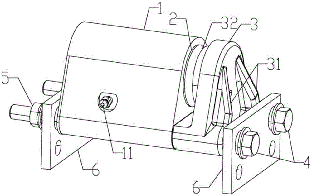
[0012] Such as figure 1 As shown, a hydraulic valve device, the brake device includes a hydraulic cylinder 1, a hydraulic wear-resistant movable plate 2, a fixed plate 3, two mounting screws 4, two mounting nuts 5 and two mounting supports Plate 6, the hydraulic cylinder 1 and the fixed plate 3 are connected with the installation screw, the hydraulic wear-resistant movable plate 2 is fixedly connected with the piston of the hydraulic cylinder 1, and the fixed The side of the plate 3 close to the hydraulic cylinder 1 is provided with a wear-resistant fixed piece 32; the surface of the hydraulic wear-resistant movable plate 2 is coated with a tungsten carbide metal layer sprayed by supersonic thermal spraying technology. The side of the fixed plate 3 away from the hydraulic cylinder 1 is provided with a reinforcing rib 31 . Both sides of the hydraulic cylinder 1 are provided with hydraulic oil circuit connection ports 11 . The two mounting support plates 6 are in contact with ...


PUM


Abstract

The invention discloses a hydraulic valve device. The braking device comprises a hydraulic cylinder, a hydraulic abrasion-proof movable plate, a fixed plate, two mounting screw rods, two mounting nuts and two mounting supporting plates, wherein the hydraulic cylinder and the fixed plate are connected with the mounting screw rods; the hydraulic abrasion-proof movable plate is fixedly connected with a piston of the hydraulic cylinder; an abrasion-proof stator is arranged on the side, which is close to the hydraulic cylinder, of the fixed plate; the surface of the hydraulic abrasion-proof movable plate is coated with a tungsten carbide metallic layer sprayed by using a supersonic hot spraying technology. The hydraulic valve device disclosed by the invention has the advantages of simple structure, acute braking, better quality, long service life and low maintenance cost.

Description

technical field [0001] The invention relates to a hydraulic valve device. Background technique [0002] The transmission of the hydraulic valve device in the prior art through the mechanical structure makes the structure of the transmission part very complicated, the cost is high and unreliable, the cost is also high, the life is short, and the user's use cost is high. Contents of the invention [0003] The purpose of the present invention is to provide a hydraulic valve device with simple structure, sensitive braking, good quality, long service life and low maintenance cost. [0004] The present invention is realized through the following technical solutions: a hydraulic valve device, the brake device includes a hydraulic oil cylinder, a hydraulic wear-resistant movable plate, a fixed plate, two mounting screws, two mounting nuts and two mounting The support plate, the hydraulic cylinder and the fixed plate are connected with the installation screw, the hydraulic wear-re...

Claims


Application Information

Patent Timeline
IPC IPC(8): F16K31/122
CPCF16K31/122
Inventor 董永军
Owner YANGZHOU JUNRUI CHUANGZHI IND DESIGN
Learn More