Explosive loading continuous multi-pulse-load loading experiment device

A loading experiment, multi-pulse technology, applied in the direction of measuring devices, mechanical devices, instruments, etc., can solve the problem of inability to evaluate the impact of explosive charge damage to the safety of explosive charge, the stress environment does not match, and the probability of "hot spots" forming increase, etc.

Active Publication Date: 2016-02-03
XIAN MODERN CHEM RES INST
View PDF6 Cites 12 Cited by
  • Summary
  • Abstract
  • Description
  • Claims
  • Application Information

AI Technical Summary

Problems solved by technology

[0004] First of all, the structure of the sample bomb can only simulate the situation where the explosive charge is subjected to a single pulse load, but cannot simulate the situation where the explosive charge is subjected to continuous multiple pulse loads, which is inconsistent with the stress environment of the explosive charge when the warhead penetrates a multi-layer target ;
[0005] Secondly, the structure of the sample bomb cannot reflect the charge damage effect during the loading process, neither can evaluate the damage caused by multi-pulse continuous load loading on the explosive charge and the impact of the damage on the safety of the explosive charge. After the first pulse action, different degrees of damage will often occur inside the charge, and the probability of "hot spots" forming in the subsequent pulse action process of the damaged charge increases, and early explosion may occur.
[0006] At present, there are no various public reports, papers and patents related to this explosive charge continuous multi-pulse load loading experimental device at home and abroad.

Method used


Image

  • Explosive loading continuous multi-pulse-load loading experiment device
  • Explosive loading continuous multi-pulse-load loading experiment device
  • Explosive loading continuous multi-pulse-load loading experiment device

Examples


Embodiment Construction

[0018] Below in conjunction with accompanying drawing and embodiment the present invention is described in further detail, it should be noted that the present invention is not limited to following specific embodiment, all equivalent transformations carried out on the basis of the technical solution of the present invention are all within the scope of protection of the present invention.

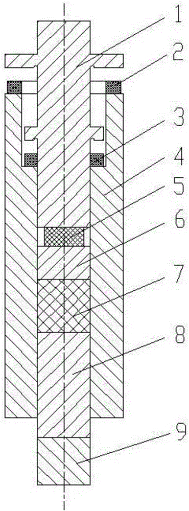
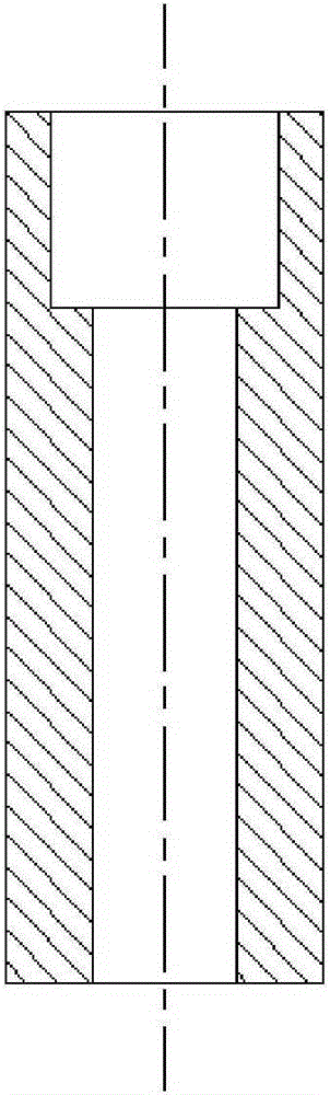
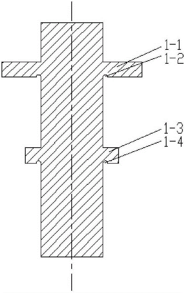
[0019] Comply with the above technical solutions, such as Figure 1-Figure 3 As shown, this embodiment provides an experimental device for continuous multi-pulse loading of explosive charges, including an upper impact column 1, a cushion pad 2, a cushion pad 3, a cushion pad 5, a sleeve 4, a middle impact column 6, and a sample 7 , hit column 8 and sensor 9 down. Among them, the upper stroke column 1 is a solid steel cylinder with a ring support 1-1 and a ring support 1-3, and is connected to the end with a larger inner diameter of the sleeve 4, and the ring support 1-1 and the ring support 1...


PUM

PropertyMeasurementUnit
diameteraaaaaaaaaa
diameteraaaaaaaaaa
radiusaaaaaaaaaa

Abstract

The invention discloses an explosive loading continuous multi-pulse-load loading experiment device which comprises an upper impact column, buffer cushions, a sleeve, a middle impact column, a sample, a lower impact column and a sensor. The upper impact column is a steel solid cylinder provided with two annular supports, and is connected with the large-inner-diameter end of the sleeve. The sleeve is a cylinder with a step through hole machined inside. The small-inner-diameter part of the sleeve is sequentially provided with the buffer cushions, the middle impact column, the sample and the lower impact column. The three buffer cushions are located at the end of the sleeve, the diameter-changing position of the step hole of the sleeve and between the upper impact column and the middle impact column respectively. The middle impact column, the sample and the lower impact column are cylinders and have the outer diameters the same as the inner diameter of the sleeve. The end, away from the upper impact column, of the lower impact column is provided with the steel cylindrical sensor. By means of the explosive loading continuous multi-pulse-load loading experiment device, continuous multi-pulse-load loading can be conducted for explosive loading, all pulse load stress peak values and loading time can be effectively controlled, the service environment where layer targets are built up during explosive loading in the payload can be more vividly simulated, and then the overload resistance safety of the device is evaluated scientifically.

Description

technical field [0001] The invention belongs to the technical field of experimental devices for explosives laboratories, and relates to a multi-pulse load loading device, in particular to a continuous multi-pulse load loading experimental device for simulating projectile penetration into a layered target. Background technique [0002] With the development of protective engineering, important strategic institutions in various countries in the world today, such as command centers, communication hubs, political buildings, etc., have a trend of strong protection and multi-layer composite protection, and all adopt underground or semi-underground structures. In terms of target characteristics, the multilayer composite protective structure can generally be equivalent to a layered target composed of soil layer, mortar block stone layer, loose material layer and reinforced concrete layer. When the warhead penetrates into the layered target, the explosive charge of the warhead will be...

Claims


Application Information

Patent Timeline
Patent Type & Authority Applications(China)
IPC IPC(8): G01N19/00
Inventor 屈可朋王辉沈飞李亮亮肖玮何超
Owner XIAN MODERN CHEM RES INST
Why Eureka
Try Eureka