
Standby control circuit, standby control method and electrical apparatus

A technology for controlling circuits and control methods, which is applied in the direction of control/regulation systems, instruments, and adjustment of electrical variables, etc., can solve the problems of increasing system standby power consumption, and achieve the effects of saving standby power consumption, low cost, and simple structure

Active Publication Date: 2016-02-03
GREE ELECTRIC APPLIANCES INC
View PDF10 Cites 1 Cited by
  • Summary
  • Abstract
  • Description
  • Claims
  • Application Information

AI Technical Summary

Problems solved by technology

When the inverter air conditioner is in the standby state, since the current still flows through the discharge resistor, this will increase the system standby power consumption

Method used


Image

  • Standby control circuit, standby control method and electrical apparatus
  • Standby control circuit, standby control method and electrical apparatus
  • Standby control circuit, standby control method and electrical apparatus

Examples


Embodiment Construction

[0025] The present invention will be described in further detail below in conjunction with the accompanying drawings and specific embodiments, but not as a limitation of the present invention.

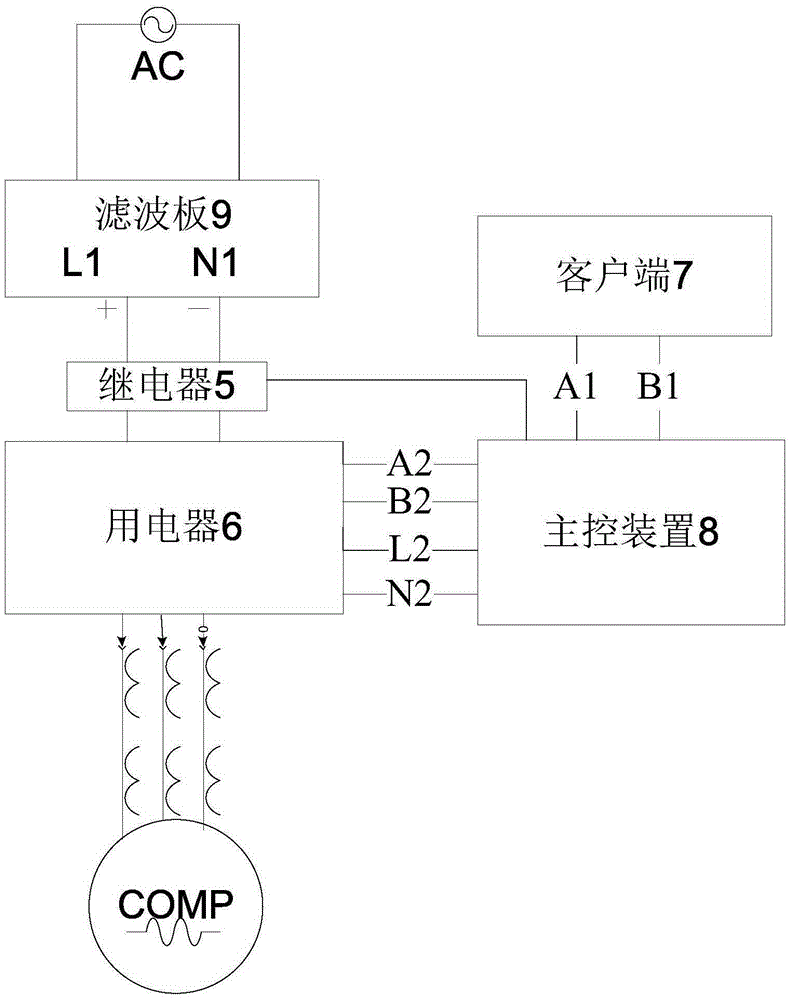
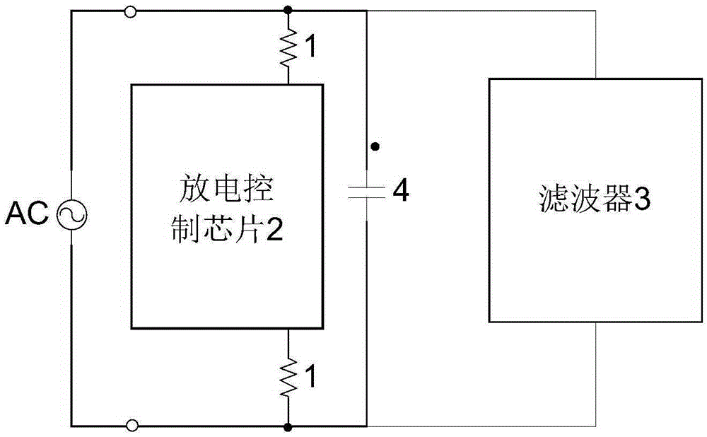
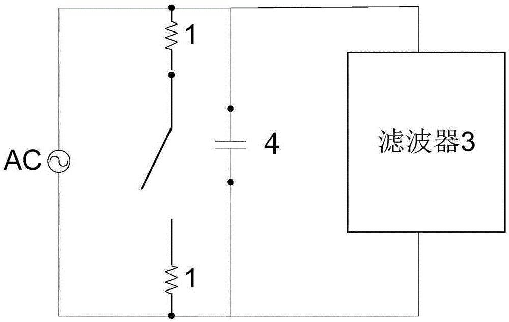
[0026] Please refer to Figure 1 to Figure 5 , the present invention provides a standby control circuit, comprising: a discharge resistor 1; a discharge control chip 2, which is connected in series with the discharge resistor 1 to form a discharge circuit for controlling the conduction of the discharge circuit when the input AC power supply AC is cut off; 3; The X capacitor 4 used to filter out differential mode interference is connected in parallel with the discharge circuit and the filter. Among them, the discharge resistor 1 , the discharge control chip 2 and the filter 3 form a filter board 9 . Preferably, the electrical appliance 6 is a frequency converter.

[0027] Please refer to Figures 1 to 5 ,exist figure 1 , 4 In and 5, A1, B1, A2, and B2 are signal wires, L1 is the li...


PUM


Abstract

The invention discloses a standby control circuit, a standby control method and an electrical apparatus. The standby control circuit comprises discharging resistors, a discharging control chip, a filter and an X-capacitor, wherein the discharging control chip and the discharging resistors are in series connection so as to form a discharging circuit; the discharging control chip is used for controlling the connection of the discharging circuit when an input AC power supply is powered off; the X-capacitor is used for filtering differential mode interference; and the X-capacitor is in parallel connection with the discharging circuit and the filter. By employing the technical scheme mentioned above, the discharging control chip can control the working state of the discharging resistors, so that the standby power consumption is saved, efficient and energy-saving effects are achieved, and the standby control circuit is simple in structure and low in cost.

Description

technical field [0001] The invention relates to the field of standby control, in particular to a standby control circuit, a standby control method and electrical equipment. Background technique [0002] The load of the frequency converter in the prior art in the standby mode mainly includes the main control device and its peripheral circuits, the drive circuit, and the filter circuit; in the standby mode, all three circuits have current flowing through them, and consume power during the production process. [0003] For the filter circuit, according to the requirements of "Safety of Household and Similar Electrical Appliances", if the residual voltage of the plug meets the standard requirements, and the X capacitor in the filter circuit exceeds 0.1uF, no discharge resistor is needed; if it cannot be satisfied, a discharge resistor must be added. until the residual pressure requirement is met. [0004] If the X capacitor exceeds 0.1uF, increase the discharge resistance, and i...

Claims


Application Information

Patent Timeline
Patent Type & Authority Applications(China)
IPC IPC(8): G05F1/40
Inventor 胡雅洁杨帆杨喜
Owner GREE ELECTRIC APPLIANCES INC
Learn More