
An optimization method for the position of the disc brake push rod

A technology of disc brakes and optimization methods, applied in instruments, special data processing applications, calculations, etc., can solve problems such as uneven force on friction blocks, reduced brake life, reduced braking torque, etc., to shorten the development cycle, Effects of drop in contact pressure and increase in braking torque

Active Publication Date: 2018-07-27
JIANGSU HENGLI BRAKE MFG
View PDF2 Cites 0 Cited by
  • Summary
  • Abstract
  • Description
  • Claims
  • Application Information

AI Technical Summary

Problems solved by technology

[0004] In the known disc brake design, the center position of the push rod coincides with the centroid of the surface of the friction block. When the brake disc is stationary, the contact pressure is uniform, and when the brake disc is in the braking state, the center of the contact pressure rotates Direction movement, deviation from the centroid of the friction block, resulting in uneven force on the friction block as a whole, resulting in severe eccentric wear; at the same time, the pressure per unit area increases, the braking torque decreases, and even insufficient braking force occurs, which makes the brake Long-term overload working state, the life of the brake is reduced

Method used


Image

  • An optimization method for the position of the disc brake push rod
  • An optimization method for the position of the disc brake push rod
  • An optimization method for the position of the disc brake push rod

Examples


Embodiment Construction

[0036] The present invention will be further explained below in conjunction with the accompanying drawings and specific embodiments.

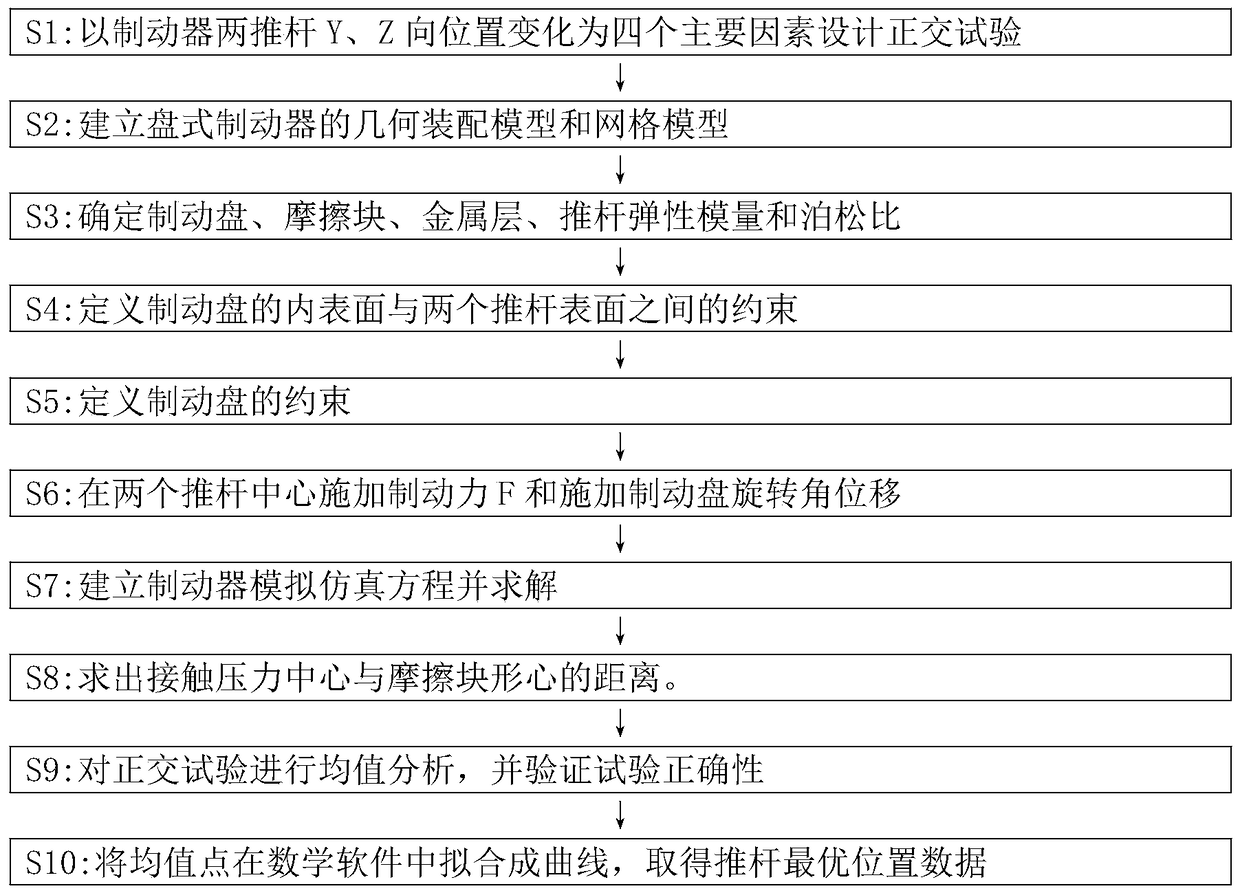
[0037] Such as figure 1 As shown, it mainly includes the following steps:

[0038] In the first step, using orthogonal test software such as minitab16, the design takes the position changes of the two push rods in the Y and Z directions as four main factors, and each factor has three factors: -6, 0, and 6 (take 10% of the width of the friction block) L9 (4 3 ) Orthogonal test.

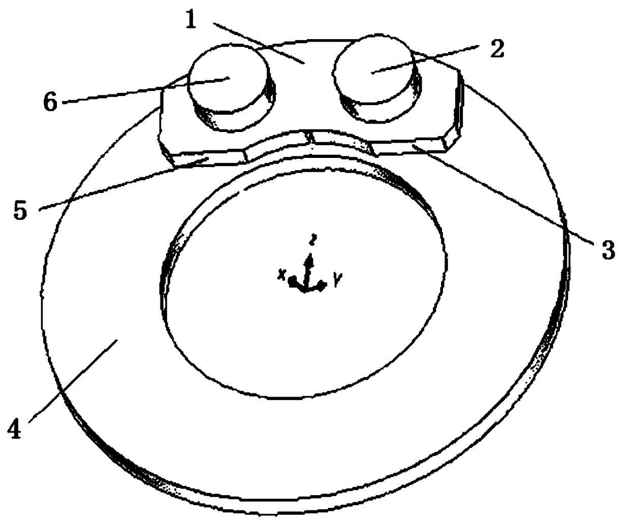
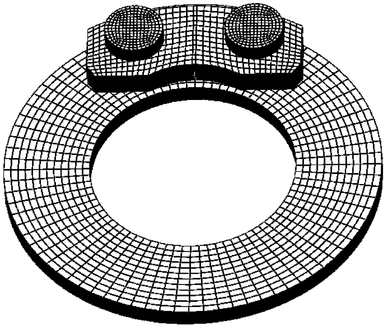
[0039] In the second step, first, use 3D software such as PROE software to establish a geometric assembly model of a 24.5-inch disc brake, such as figure 2 As shown, draw metal layer 1, No. 2 push rod 2, No. 2 friction block 3, brake disc 4, No. 1 friction block 5 and No. 1 push rod 6. Then use model generation software such as Hypermesh software to generate the hexahedral mesh model of the brake disc, friction block, metal layer, and push rod, where the friction b...


PUM


Abstract

The invention discloses a method for optimizing the position of a push rod of a disc brake. The steps are as follows: 1. Design an orthogonal test based on the position changes of two push rods of the brake in the horizontal direction Y and the vertical direction Z; 2. Establish Geometric assembly model and grid model of the disc brake; 3. Determine the elastic modulus and Poisson's ratio of the brake disc, friction block, metal layer and push rod; 4. Define the inner surface of the brake disc and the two push rod surfaces 5. Apply normal symmetric constraints on the symmetric plane of the brake disc; 6. Apply the braking force F to the center of the two push rods, and apply the rotational angular displacement to the center of the brake disc; 7. Establish the movement of the disc brake Calculate the equation by simulation and solve the equation; 8. Calculate the distance between the contact pressure center and the centroid of the friction block; 9. Verify the result; 10. Obtain the optimal position data of the push rod. The invention considers to eliminate the subjectivity of the design of the push rod position in the design of the disc brake, and can correctly obtain the optimum push rod position.

Description

technical field [0001] The invention belongs to the technical field of disc brakes, in particular to an optimization method for the position of a push rod of the disc brake. Background technique [0002] Disc brakes are widely used in automobiles and ships because of their advantages such as large braking torque, good thermal stability, good braking performance and water stability, small size, small wear, easy automatic adjustment of gaps, and convenient maintenance operations. and other industries. [0003] During the braking process of the disc brake, the air pressure generated by the air chamber is amplified by the lever and acts on the inner friction block through the double push rods, pushing the inner friction block to press against the rotating brake disc, so that the kinetic energy of the disc brake is converted into heat energy to To achieve the purpose of braking, the push rod mainly plays the role of transmitting load. The change of the position of the push rod w...

Claims


Application Information

Patent Timeline
Patent Type & Authority Patents(China)
IPC IPC(8): G06F17/50
Inventor 谭雪龙张建李金泰朱永梅唐文献晏飞
Owner JIANGSU HENGLI BRAKE MFG
Learn More