T-shaped/inclined-L-shaped current guide slit dual-frequency broadband dual-circular polarization microstrip laminated antenna

A dual circular polarization and slot technology, applied in antennas, antenna grounding switch structural connections, and devices that enable antennas to work in different bands at the same time, can solve the problem of dual-frequency circular polarization microstrip antennas with few successful examples, antennas High profile, large size, etc., to meet the needs of integrated transceiver, compact structure, and excellent gain performance

Active Publication Date: 2016-02-03
XIAMEN UNIV
View PDF3 Cites 24 Cited by
  • Summary
  • Abstract
  • Description
  • Claims
  • Application Information

AI Technical Summary

Benefits of technology

This new design improves on current satellites' ability to communicate wirelessly by utilizing specialized components called radiating elements that are placed inside an outer casing made up of materials like plastic or metal. These improvements make it easier than previous designs due to its small size, lightweight construction, ease of manufacturing, high frequency response capabilities, and good signal quality at Ku bands (C) used throughout this patented communication range.

Problems solved by technology

The technical problem addressed in this patented text relates to improving the functionality and capabilities of small satellites for broadcast television signals while maintaining compatibility among multiple types of signal sources like GPS and GLONASS devices.

Method used


Image

  • T-shaped/inclined-L-shaped current guide slit dual-frequency broadband dual-circular polarization microstrip laminated antenna
  • T-shaped/inclined-L-shaped current guide slit dual-frequency broadband dual-circular polarization microstrip laminated antenna
  • T-shaped/inclined-L-shaped current guide slit dual-frequency broadband dual-circular polarization microstrip laminated antenna

Examples


Embodiment Construction

[0028] The present invention will be further described below in conjunction with the embodiments and accompanying drawings.

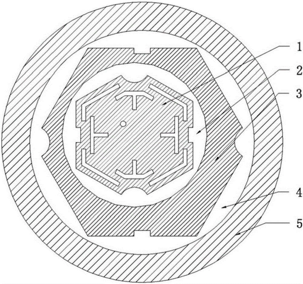
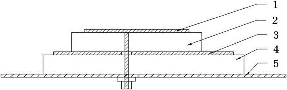
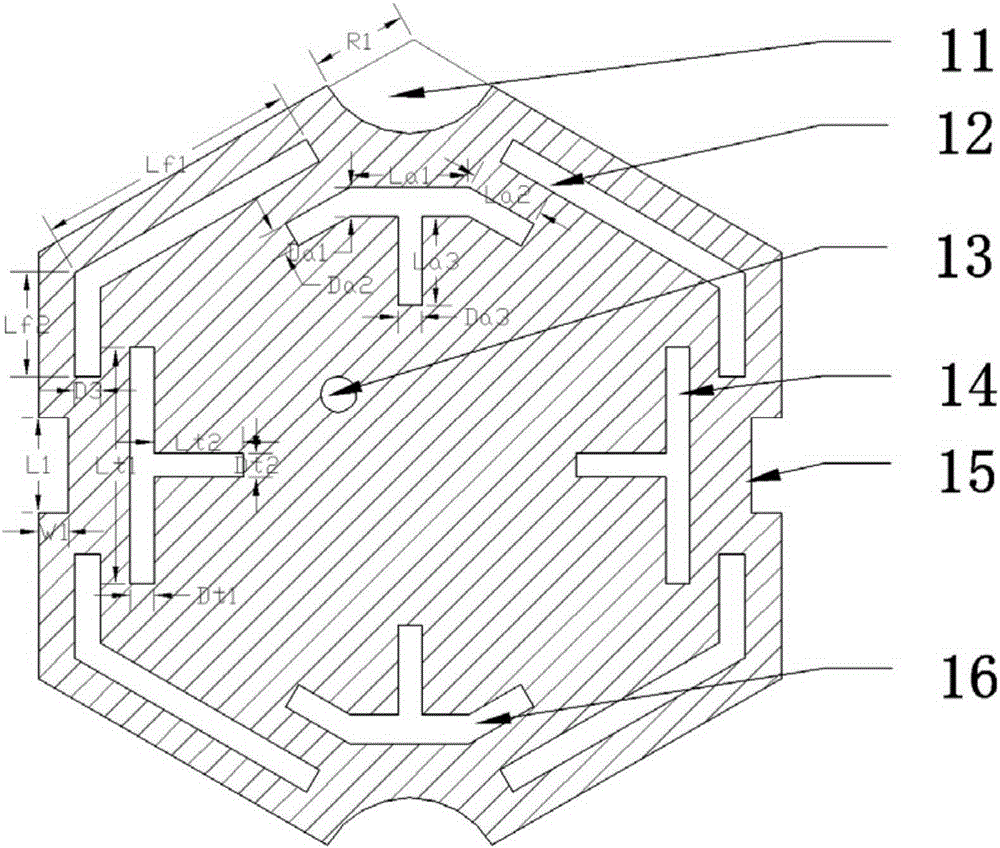
[0029] see Figure 1~4, the embodiment of the present invention consists of an upper patch 1 , an upper dielectric substrate 2 , a lower patch 3 , a lower dielectric substrate 4 and a ground plate 5 . Embodiment The dielectric constant of the dielectric substrate 1 is 6.15, the radius is 13.0-21.0 mm, a typical value is 15.4 mm, and the thickness is 2.5-3.5 mm, a typical value is 3.0 mm. The dielectric constant of the dielectric substrate 2 is 6.15, the radius is 18-30 mm, typically 24 mm, and the thickness is 2.5-3.5 mm, typically 3.0 mm. The structural outline of the upper patch 1 is hexagonal, with a side length of 13.0-21.0mm, typically 14.5mm; the hexagonal patch is cut with arc grooves 11 diagonally above and below, and with rectangular grooves 15 cut on the left and right sides , the apex of the arc groove is located at the apex of the hexagon,...


PUM

PropertyMeasurementUnit
Radiusaaaaaaaaaa
Thicknessaaaaaaaaaa
Radiusaaaaaaaaaa

Abstract

The invention relates to a T-shaped/inclined-L-shaped current guide slit dual-frequency broadband dual-circular polarization microstrip laminated antenna and belongs to the broadband microstrip antenna field. The microstrip laminated antenna is provided with an upper layer dielectric substrate, a lower layer dielectric substrate and a grounding plate; an upper layer patch is laid on the upper surface of the upper layer dielectric substrate; the upper layer patch is a hexagon-shaped radiation patch, circular grooves being cut at upper and lower opposite angles, rectangular grooves being cut at left and right opposite edges; oblique L-shaped slits are formed between the circular grooves and the rectangular grooves; T-shaped slits or slits of which the shape is similar to T are formed between the oblique L-shaped slits; two ends of the horizontal part of each slit of which the shape is similar to T are provided with folded line structures; through the loading of the T-shaped slits, the slits of which the shape is similar to T and the oblique L-shaped slits, the flowing direction of current at the surface of the antenna can be guided, and therefore, the gain performance of the antenna can be optimized; a lower layer patch is laid on the upper surface of the lower layer dielectric substrate; the lower layer patch is a hexagon-shaped radiation patch, circular grooves being cut at right and left opposite angles, rectangular grooves being cut at upper and lower opposite edges; the upper layer patch is arranged in a leftward eccentrically manner relative to the lower layer patch, so that the resistance matching of the single-feed laminated multi-frequency antenna can be realized; and a coaxial feed opening is formed at the upper layer patch.

Description


Claims


Application Information

Patent Timeline
Owner XIAMEN UNIV
Why Eureka
Try Eureka