Actuator for rendering at least one optical element movable

A technology of optical components and actuators, which is applied in the direction of optical signals, electrical components, transmission devices, etc., can solve the problems affecting the positioning of movable optical components, and cannot eliminate the radial gap and axial gap of the worm, so as to achieve the goal of improving positioning Effect

Active Publication Date: 2016-02-03
AML SYST
View PDF6 Cites 2 Cited by
  • Summary
  • Abstract
  • Description
  • Claims
  • Application Information

AI Technical Summary

Problems solved by technology

However, such springs cannot eliminate the radial play of the worm (defined by the angle of rotation around the axis of the worm) and the axial play of the worm (defined by the translation parallel to the axis of rotatio

Method used


Image

  • Actuator for rendering at least one optical element movable

Examples


Embodiment Construction

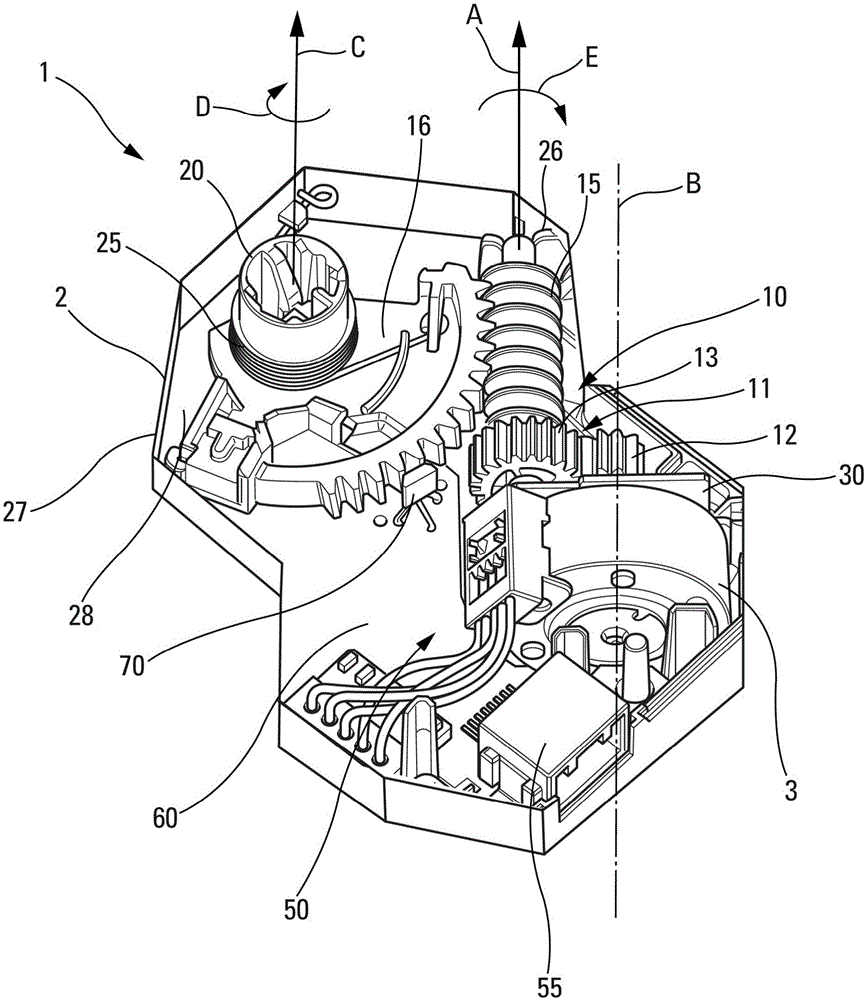
[0027] The present invention involves such as figure 1 Shown is an electric actuator 1 for moving an optical element. This electric actuator 1 comprises housing 2 ( figure 1 Only the lower half of the housing 2 is shown). The housing 2 includes a bottom plate 28 and a peripheral wall 27 .

[0028] The electric actuator 1 also includes an electric motor 3 , a mechanical transmission assembly 10 and a drive device 20 . A mechanical transmission assembly 10 is arranged to transmit the motion of the electric motor 3 to a drive 20 . The drive means 20 is configured to be connected to an optical element (not shown) and to transmit the motion of the motor to the optical element. Here, the motor 3 drives the mechanical transmission assembly 10 via the shaft of the motor arranged to rotate about the axis B. As shown in FIG. Movable optical element means any optical element of a vehicle headlight, in particular a motor vehicle headlight, which is movable for the purpose of changing...


PUM


Abstract

The invention relates to an electric actuator (1) to render optical elements movable. The electrical actuator generally has a motor (3), a mechanical transmission assembly (10) having an endless screw (15), a support element of the endless screw (15), a drive mechanism (20), and a return mechanism (25). The motor (3) is configured to drive the mechanical transmission assembly (10) and the mechanical transmission assembly (10) is configured to drive the drive mechanism (20), wherein the return mechanism (25) exerts an axial pressure against the endless screw (15) in such a way as to press the endless screw (15) against the support element. The disclosure also relates to an assembly having a movable optical element and an electric actuator (1) of the movable optical element as described above.

Description

technical field [0001] In the field of automotive lighting, DBL-style (dynamic bending light, dynamic turning lighting) cornering headlights or movable optical elements are known with adaptive lighting functions for ADB ((adaptive driving beam, adaptive high beam) lamps. Background technique [0002] To move the optical elements, electronic actuators consisting of motors and gears are usually used. In order to step down the maximum amount of output motion from the motor in the minimum space, it is known to provide a gear transmission having a worm at the output of the motor and transmitting the motion of the worm to a movable optical Elements of spur gears. However, to function efficiently and for mass production reasons, the actuator has a lot of toothplay between the different parts of the gearing. This large amount of backlash has a direct effect on the positioning accuracy of the optical element. [0003] For widely used LED light sources and emerging laser light sour...

Claims


Application Information

Patent Timeline
IPC IPC(8): H02K7/116F16H37/04
CPCB60Q1/076F16H57/12F16H2057/126F16H2057/0213F16H19/08F16H57/021
Inventor 克劳迪奥·奇亚特立西里尔·瑞维尔哈桑·寇劳
Owner AML SYST
Why Eureka
Try Eureka