
Method for making slide sleeve ring

A technology for sliding sleeves and pressed products, applied in the field of sliding sleeve rings, can solve the problems of time-consuming and expensive processing of geometric structures

Inactive Publication Date: 2016-02-10
HOERBIGER ANTRIEBSTECHN HLDG
View PDF7 Cites 5 Cited by
  • Summary
  • Abstract
  • Description
  • Claims
  • Application Information

AI Technical Summary

Problems solved by technology

The disadvantage, however, is that the pre-sintered component already has a relatively high strength, so that the machining for inserting the required geometry is time-consuming and expensive

Method used


Image

  • Method for making slide sleeve ring
  • Method for making slide sleeve ring
  • Method for making slide sleeve ring

Examples


Embodiment Construction

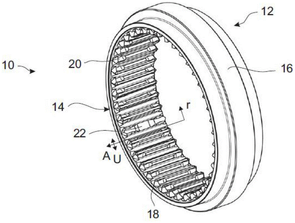
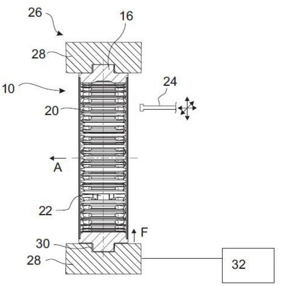
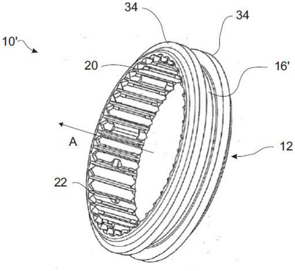
[0029] figure 1 The machined compact 10 of the sliding sleeve ring 12 of the sliding sleeve is shown. In the sintering method, the sliding sleeve ring of the finished sliding sleeve is formed from the sliding sleeve ring 12 substantially without changing its outer contour. Since the sintered sliding sleeve ring appears identical to the processed compact 10 , the finished sliding sleeve ring is not shown separately here.

[0030] To produce the pressed product 10 , first the powdered metal material is pressed under pressure in a tool (not shown). Suitable metals are eg ferrous materials. The powder used should be as random as possible, so that a sufficiently high blank strength can be achieved.

[0031] The pressed product 10 obtained in this way already has the basic shape of the finished sliding sleeve ring 12 . The inner toothing 14 for the selector fork on the radially outer peripheral side and the meshing geometry 16 in the form of an annular radially protruding shift ...


PUM


Abstract

The invention relates to a method for making a slide sleeve ring; metal powders are sintered so as to form the slide sleeve ring (12) through moulding; pressed product (10) can be made under pressure effect in a pressing process, can be cut and processed under pressing fixed state, and is sintered so as to form the moulding piece.

Description

technical field [0001] The invention relates to a method for producing a sliding sleeve ring in the form of a sintered molded part of a transmission. Background technique [0002] A sliding sleeve ring is used in the synchronizing unit to produce a rotationally fixed connection between the synchronizing body and the gearwheel to be shifted. The sliding sleeve ring is an annular part with an internal toothing which engages simultaneously with external toothing on the synchronizing body and on the gear wheel, and an external toothing geometry on which the shift fork acts. Structurally, the sliding sleeve ring is thus displaced in the axial direction in the direction towards the gearwheel and pushed away from it when the gear is disengaged. [0003] Traditionally, sliding sleeves are produced from pipe sections by rolling, rolling and cutting processes. It is also possible to pre-form a forged blank which is then chipped to complete the machining. [0004] It is also known t...

Claims


Application Information

Patent Timeline
Patent Type & Authority Applications(China)
IPC IPC(8): B22F5/08B22F3/16B23P15/00
CPCB23P15/14B22F3/10B22F5/08B22F5/106B22F2005/005B22F2998/10B22F2999/00B22F3/02B22F2003/247
Inventor 维尔纳·菲尔古特彼得·埃科特勒赫尔曼·陶赖纳·尼采迪特马尔·克劳斯
Owner HOERBIGER ANTRIEBSTECHN HLDG
Learn More