Cable trough combination for rail transit system

A rail transit and cable trough technology, applied in the mechanical field, can solve problems such as complex sealing and fitting structure, difficult heat dissipation and drainage, and inconvenient installation, and achieve good waterproof effect, enhanced heat dissipation and drainage effect, and convenient maintenance

Active Publication Date: 2016-02-10
NINGBO HUAYUAN FRP ELECTRICAL APPLIANCE MFR
View PDF8 Cites 3 Cited by
  • Summary
  • Abstract
  • Description
  • Claims
  • Application Information

AI Technical Summary

Problems solved by technology

[0003] At present, the following three laying schemes can be adopted for the laying of strong electric cables on ground lines: laying concrete cable shallow grooves, laying cable brackets with sunshades, and laying composite material cable troughs, all of which have good sun protection effects, but the laying is still difficult. It is necessary to consider the cable laying space requirements for the cable cross section and the number of cables. Due to the small volume and low total weight of the composite material cable tray, most of the composite material cable trays are currently laid, including the U-shaped cable tray bottom and the cable tray. However, due to the consideration of sealing and sun protection in the laying and installation of composite cable troughs, the sealing and matching structure of the bottom of the cable trough and the cover of the cable trough is more complicated, and the installation is inconvenient, and there are certain difficulties in heat dissipation and drainage.

Method used


Image

  • Cable trough combination for rail transit system
  • Cable trough combination for rail transit system
  • Cable trough combination for rail transit system

Examples


Embodiment Construction

[0023] The present invention will be further described below in conjunction with the accompanying drawings and specific embodiments.

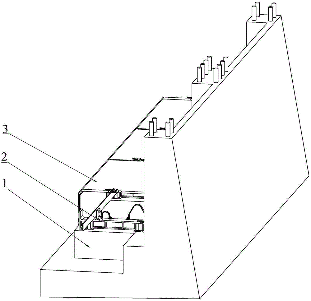
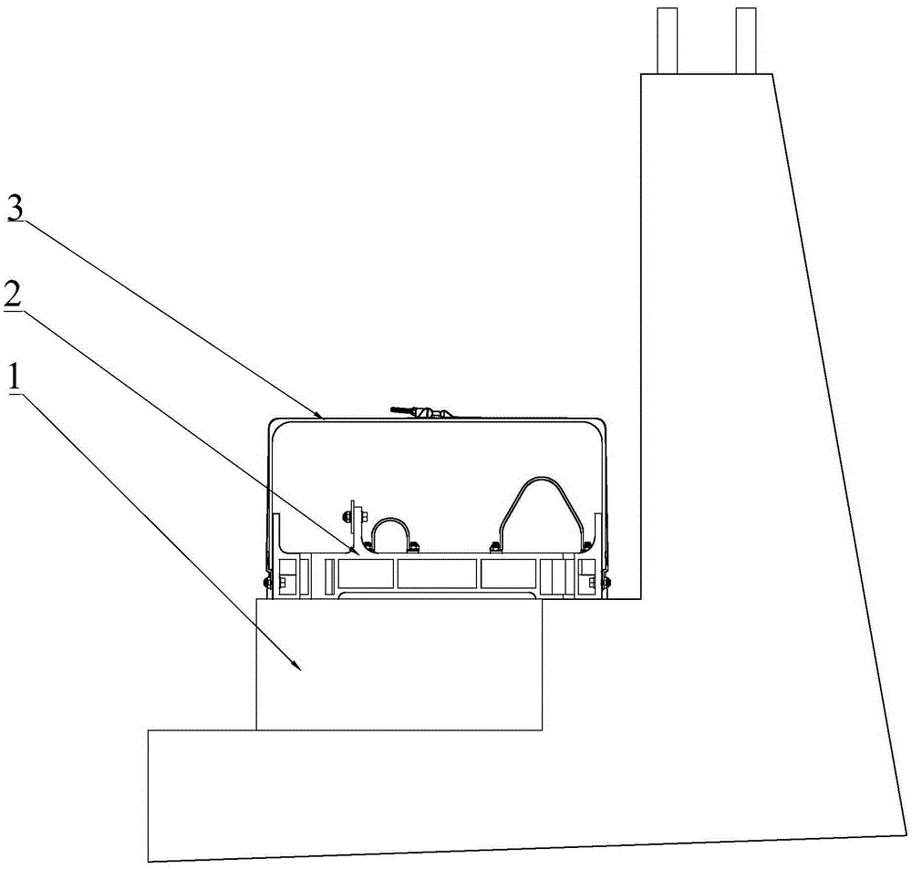
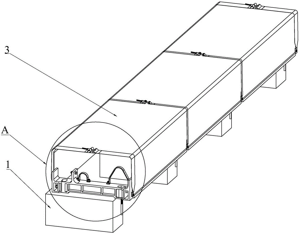
[0024] see figure 1 , figure 2 , image 3 , Figure 4 and Figure 5 As shown, the cable trough combination for rail transit system of the present invention includes several connected cable trough combination monomers, and the cable trough combination monomer includes several support blocks 1 arranged at intervals, fixedly connected on the top of the support block 1 The cable groove support 2 for supporting cables, the top of the support block 1 supports an inverted U-shaped cable groove cover 3 with openings at both ends, and the cable groove support 2 is located in the cable groove cover 3 and is connected with the The cable groove cover 3 is connected by first setting the support block 1, then fixing the cable groove bracket 2 on the support block 1, and finally fastening the inverted U-shaped cable groove cover 3 on the cable groove bra...


PUM


Abstract

The invention discloses a cable trough combination for a rail transit system, and aims to provide a cable trough combination which is sunproof, rainproof, good in heat-dissipating and waterproof effect, and convenient and fast to use, install and maintain and is used for the rail transit system. The cable trough combination is characterized by comprising multiple connected cable trough combination units, and each cable trough combination unit comprises multiple cable trough supports arranged at intervals and an inverted-U-shaped cable trough cover used for shielding the cable trough supports and provided with openings in the two ends, wherein the cable trough supports are located in the cable trough cover and connected with the cable trough cover, the weight and the size of an installed device in the first step are reduced, installation is more convenient and easy to adjust, the installation accuracy is greatly improved in a narrow space particularly, the probability of reinstallation caused by mismatching installation is reduced, the working efficiency is improved, and follow-up overhauling and maintaining are facilitated.

Description

technical field [0001] The invention relates to the technical field of machinery, and relates to an above-ground interval cable trough in an electrified railway or urban rail transit system, in particular to a cable trough combination for a rail transit system. Background technique [0002] The laying environment of the ring network cable in the ground section is harsh. If it is directly exposed to the air, it will be exposed to wind, sun, and rain for a long time. Due to the performance limitations of insulation and outer sheath materials, the outer sheath of the cable or even the cable insulation rupture still occurs in the actual operation line. Once the insulation of the ring network cable is damaged, the system will be short-circuited, the power supply system will be paralyzed, and the entire urban rail system will be paralyzed, with serious consequences. The replacement of the ring network cable is not only a huge workload for the lines in operation, but also seriousl...

Claims


Application Information

Patent Timeline
Patent Type & Authority Applications(China)
IPC IPC(8): B60M1/20H02G3/04
Inventor 李立颖邹东周良华周方展俞碧波张宵华刘颖
Owner NINGBO HUAYUAN FRP ELECTRICAL APPLIANCE MFR
Why Eureka
Try Eureka